Wow, DIY flux. I use non activated rosin core, but don't make my own. Let us know how it works out.
I might try mixing some of the pine rosin I bought recently with isopropyl and petroleum jelly to see how that goes as flux.
It could be used as DIY body lotion as well 😀
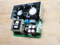
These Würth xformers work nicely. I designed a high efficient 400W LLC with synchronous rectification (single supply voltage for full bridge TPA3255). If you are interested I could support you with empty sample PCBs and documentation (KiCAD Design).I note you don't even have to wind your own transformers these days...
Wurth Elektronik WE-LLCR Series Power Transformers – Mouser Australia
Attachments
It could be used as DIY body lotion as well 😀
Nah, not really.
The home made flux works really well.
I started by dissolving 25g of pine rosin in 100g of isopropyl alcohol. That was very runny. It worked okay as liquid flux, but required several applications with a brush to get on to a decent thickness.
So I tried to see how much rosin I could dissolve in 100g of iso. I’m at 100g currently, but after about six hours there’s a little still undissolved. That’s a pretty good liquid flux. Reasonable thickness, and applies well with a brush.
I like using paste flux, as it's got a longer working time before it goes hard. According to the MSDS for a bunch of rosin paste fluxes, they’re a mixture of rosin and either lanolin or petrolatum (petroleum jelly aka Vaseline). I tried initially dissolving rosin in Vaseline, but the Vaseline is a crap solvent.
Then I tried an already dissolved rosin (50/50 rosin/iso), and added some Vaseline, so it’s about 35% rosin, 35% iso, 30% Vaseline. That worked very well. I put the runny paste in the oven for a couple of hours and evaporated some iso, and it’s even better. It’s still a bit runnier than the commercial pastes, but it performs exactly the same on the board. I can dispense good amounts without it going everywhere, and it produces beautiful bright joins. I shall make a pile of this stuff.
Attachments
Last edited:
Looking good Suzy!
The weekend is right around the corner, might there be reports of first sound?? 😀
The weekend is right around the corner, might there be reports of first sound?? 😀
Alas no. I have no stock of high-voltage NP0 ceramic caps, nor big bipolar transistors, nor a bunch of other bits. I'm waiting on a Mouser order that's scheduled for delivery Monday.
And then there's the matter of organising power for them. I can lash something together to provide the four rails that will suffice for initial setup, but it won't be adequate for proper testing. I need to build some power supplies.
And then there's the matter of organising power for them. I can lash something together to provide the four rails that will suffice for initial setup, but it won't be adequate for proper testing. I need to build some power supplies.
Ok, sounds like a plan.
Will you cobble together a pair of linear supplies with different voltage transformers?
Will you cobble together a pair of linear supplies with different voltage transformers?
For setup and testing I'm madly designing a lab supply that I can build four of, to give me any rail I want from a big 500KVA toroid up to 60V, 6A (or thereabouts) - see Lab supply using Lateral MOSFETs
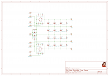
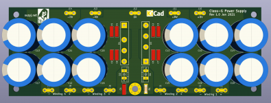
For the final product I'm designing a straightforward four rail supply using an identical pair of toroids, as shown below. One of the neat things about class G with the lower voltage rails is that I have a ready-made supply for running lower voltage stuff like preamps and active crossovers etc.
For the final product I'm designing a straightforward four rail supply using an identical pair of toroids, as shown below. One of the neat things about class G with the lower voltage rails is that I have a ready-made supply for running lower voltage stuff like preamps and active crossovers etc.
Attachments
Perreaux had a neat solution for this in their pre-amp design
I may have a schematic if you8 want a look ......🙂
I may have a schematic if you8 want a look ......🙂
Their preamps are interesting, the gain stages are little lateral mosfet power amps based on the Hitachi application note. Their power amps use the same topology.
Last edited:
Interesting indeed.
Dual rails 45V and 90V with the mosfet output stage (capacitor coupled)
Robust design that served them well for many years
Dual rails 45V and 90V with the mosfet output stage (capacitor coupled)
Robust design that served them well for many years
Interesting indeed.
Dual rails 45V and 90V with the mosfet output stage (capacitor coupled)
Robust design that served them well for many years
Please share the design. Thanks.
If you want to share those ....very interesting,especially when a ready made transformer is available!😉These Würth xformers work nicely. I designed a high efficient 400W LLC with synchronous rectification (single supply voltage for full bridge TPA3255). If you are interested I could support you with empty sample PCBs and documentation (KiCAD Design).
in my experience almost all of an amplifiers power use is either with nothing playing because I forgot to turn it off, or with perhaps a watt or two going into the speakers.
I've solved this by using the RPi to control the mains power (well, everything really)
Switches on when playback is started and off at a set time after playback has stopped (30 min for me)
My system uses a small power switch for only controlling the Pi power, while use high power relays for the amp mains that the Pi controls, soft start relay included all with times in code control.
Shes nifty and all in one. Been using shairport-sync for over a year and a half flawlessly (which you apple folks would like).
Works with apple tv and any other apple device ( and linux for me)
It is now a spotify connect device with very good and better performance so far.
She is on the level of professional and in perhaps her final beta.
BTW, LTspice works on Linux as well

Sm3 ( basically the same as the sm2) first post of this thread
Loading plugs Perreaux SM3 Preamp
All stages look identical to the Hitachi Lateral Mosfet application note from the late 70's later distributed by Maplin as DIY kits.
Attachments

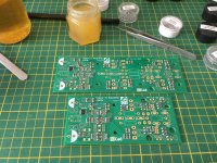
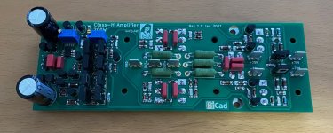
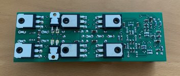
Some progress. The PCB goes together without issues.
I've fully populated the 200W version, and the 100W version is most of the way there. I forgot to order 100K and 47K 1W 0207 MELFs, so I've substituted 400mW 0204 parts instead for those for now. In each case the resistors are only dissipating ~120mW, so it'll work at least for testing purposes. I'll swap 1W parts in later.
I can test it as a class-AB by simply using the same supply for both MV and HV rails, so I'll probably do that initially while I keep designing and building supplies.
Attachments

- Home
- Amplifiers
- Solid State
- A small Class-H Lateral MOSFET amplifier