I have a question on your R48 and R49 must be... remark in the schematics next to the NFB voltage divider. It's obvious that this was done in some hurry. Did you mean the NFB divider resistors instead?
Best regards!
Best regards!
Oh absolutely, the schematic started life as my 100W class AB. It’s not final yet, not by a long shot. I expect some fiddling with compensation caps etc, before I’m happy with it.
Once I’ve got it bedded down and am confident of its stability, I’ll publish a new schematic, plus parts list etc., plus of course a whole pile of plots of performance. Until I do that this is just a simulation.
One of the cool things about this design is that I can run it as a 100W class AB, just by running both rails at 56V. I’m excited about trying that, as this amp shows promise to significantly beat the performance of my existing 100W design, at least in simulation.
shows promise to significantly beat the performance of my existing 100W design,
How is that even possible ???
How is that even possible ???
At 200W out, I measure input power as 305W, so 65%.
And I just learned an incredibly cool thing with LTspice. CMD-click on a component (I'm a mac user, you windows scum will have to figure out something else), and LTspice plots the instantaneous power dissipated by the component. Then CTRL-click on the equation in the plot, and it gives you average across the plot. So now I can quickly check if my parts are melting off the board.
Alt-Click on Windows for the power plot. Pesky Mac types 😉
(I ported games to Macs for 20 years 😉
Quick question.
R51, C16 (R46, C12) and C15 (C11) ... why are they here? And C13, C17 aswel. To prevent local RF oscillation or? In ASC file you didn't put them there but in schematic with Exicon laterals they are there.
Any reason for them with your experience or?
Regards
R51, C16 (R46, C12) and C15 (C11) ... why are they here? And C13, C17 aswel. To prevent local RF oscillation or? In ASC file you didn't put them there but in schematic with Exicon laterals they are there.
Any reason for them with your experience or?
Regards
They help to keep any HF picked up within the circuit out of the MOSFET gates. It's a circuit element that I started doing many years ago, and have kept mainly because it doesn't do anything that harms things.
They're probably entirely unnecessary. The difference between P and N channel is simply because the P-FET has much higher gate capacitance.
I put them from gate to source because that's got a lot less voltage on it than gate to drain. Caps between gate and drain can be a lot smaller (due to gain), but have to withstand the full rail-rail voltage.
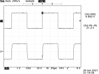
It's an amplifier!
This is the 100W flavour, with both rails driven from +/-40V, and a 2V pk-pk 10KHz squarewave on the input.
I am yet to put it on a heatsink, and am yet to really work on DC bias, so this is _very_ preliminary. However it's nice to see it's not an oscillator. This goes a decent way to validating the folded cascode on the front end, at any rate.
Time for bed now!
Attachments
Both my 100W and 200W flavours are running very happily. I had to remove the G-S cap across the N-FETs, as that was causing it to burst into song with heavy loads.
Still waiting on parts to build power supplies to test properly, but I've done lash-ups of both class AB and class G supplies, and everything switches nicely.
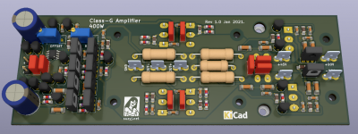
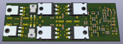
I've installed a new version of KiCad, and I took the opportunity to build some decent 3D models for transistors, starting with the TO-126 (no, they don't have 0.1" spaced pins), then TO-220 in horizontal tab-up format (I mount a lot of power devices on the underside with their tabs away from the PCB - this makes it easy to heatsink the mess). So then I did TO-247, TO-3P (I know, they're so similar to TO-247 it's not really worth the bother) and... TO-264.
So once I had the TO-264 model I needed a board to try it out on, so meet my completely ridiculous why would you ever need that 400W class G amp, which is quite simply a 200W one with bigger double-die MOSFETs. It's 8mm longer and 5mm wider than the 200W version.
400W into 8Ω needs +/-90V supplies, which is getting mighty close to the 200V Vds spec for the transistors. But hey, I could build a pair of these with lower 70V supplies and bridge them, and use that to set fire to stuff.
Still waiting on parts to build power supplies to test properly, but I've done lash-ups of both class AB and class G supplies, and everything switches nicely.
I've installed a new version of KiCad, and I took the opportunity to build some decent 3D models for transistors, starting with the TO-126 (no, they don't have 0.1" spaced pins), then TO-220 in horizontal tab-up format (I mount a lot of power devices on the underside with their tabs away from the PCB - this makes it easy to heatsink the mess). So then I did TO-247, TO-3P (I know, they're so similar to TO-247 it's not really worth the bother) and... TO-264.
So once I had the TO-264 model I needed a board to try it out on, so meet my completely ridiculous why would you ever need that 400W class G amp, which is quite simply a 200W one with bigger double-die MOSFETs. It's 8mm longer and 5mm wider than the 200W version.
400W into 8Ω needs +/-90V supplies, which is getting mighty close to the 200V Vds spec for the transistors. But hey, I could build a pair of these with lower 70V supplies and bridge them, and use that to set fire to stuff.
Attachments

I've decided we need a new metric, of power to board area. Bigger numbers are better. My boards so far do:
50W class AB: 37.5cm^2, 1.3W/cm^2.
100W class AB: 50.0cm^2, 2W/cm^2.
100W class G: 66cm^2, 1.5W/cm^2.
200W class G: 88cm^2, 2.3W/cm^2.
400W class G: 101cm^2, 4.0W/cm^2...
50W class AB: 37.5cm^2, 1.3W/cm^2.
100W class AB: 50.0cm^2, 2W/cm^2.
100W class G: 66cm^2, 1.5W/cm^2.
200W class G: 88cm^2, 2.3W/cm^2.
400W class G: 101cm^2, 4.0W/cm^2...
I'd appreciate if you could report on your power output vs rail voltages at both 4 and 8 ohm Suz.
I am interested in seeing what kind of performance and losses you have in your design.
S
I am interested in seeing what kind of performance and losses you have in your design.
S
My Mac minis are all 2014 vintage. If they were slow I’d buy an M1, but they aren’t.
Just read your post, you don't know what is fast until you work with the M1. I have one and I love it. It has a few bugs as many recent Apple products have though.
I already bought a 6 core Dell pc but the day I sold my old Mac mini I5 the new M1 was introduced. Although I had enough of Apple (Photos screwed up my pictures many times) I decided to buy one as they looked promising on paper but in reality they do deliver. Knowing this is the first Apple ARM CPU and then this performance.... it can only become better.
Something that I’d forgotten about windows, but was recently reminded now that I’m paying the bills for a fleet of the damned things at work was how little the operating system does. You want to work with PDF? You’ll need to buy Adobe for that. Zip stuff? Winzip. Process words? You’ll need office, and you can’t even buy that, it’s a subscription. Plus the virus scanning.
My Mac does all that straight out of the box. And the upgrades are completely free.
Windows 10 is a good OS and it has a free and good virus scanner included, reads PDF's just like a Mac does and also zips and unzips with a built in Windows tool. For basic office tasks there is free Libreoffice... Sorry but macOS and W10 are more alike than one might think. Even the update model is alike, W10 updates are in reality just like macOS updates and replace the old W10 version and they're also completely free. MacOS is only free when you buy an expensive Mac, in fact you can only get the OS with a Mac.
Last edited:
Anything new here?Once I’ve got it bedded down and am confident of its stability, I’ll publish a new schematic, plus parts list etc., plus of course a whole pile of plots of performance. Until I do that this is just a simulation.
Not really. I went and bought a house, so all my free time has been going into tgst.
I just read through the rest of the thread more carefully. Without actually calculating anything yet, I think i could just swap in the double-die MOSFETs, keep the +-70 v power rails and have roughly 400W into 4Ω.
4ohms is pretty standard for bass rigs and keeping the rails at +-70V keeps Vds safely away from the 200V spec for the transistors
4ohms is pretty standard for bass rigs and keeping the rails at +-70V keeps Vds safely away from the 200V spec for the transistors
With +-70V, and driving two pairs of double dies, are you still within SOA for the 1381/3503?
They are a pretty good and robust 300V device, and a short or overload on the output does not have the same implications as on a BJT output as the mosfet is a capacitive load.
They are a pretty good and robust 300V device, and a short or overload on the output does not have the same implications as on a BJT output as the mosfet is a capacitive load.
Hey Suzy, congrats on the house purchase!Not really. I went and bought a house, so all my free time has been going into tgst.
Sorry I'm almost a year late, but I've just discovered your various threads, and what you've designed looks like the perfect application for my handful of 2SJ162/2SK1058 devices!
Just wondering if you plan to (or already have?) share the KiCAD files etc. for this design (100W class G)? I love the idea of increased efficiency. Or would you suggest sticking with your previous 100W and 60W class AB designs for now?
Thanks 🙂
Hmm.. would be nice to have a KICAD file. but i am also happy with a Class G/H gerber 😉
but i think that it is a huge effort to do so like Suzji did...planning , designing, KICAD, build and testing and the posting.....give answers..etc.
she will decide...
kr
chris
but i think that it is a huge effort to do so like Suzji did...planning , designing, KICAD, build and testing and the posting.....give answers..etc.
she will decide...
kr
chris
Given you asked nicely:Hey Suzy, congrats on the house purchase!
Sorry I'm almost a year late, but I've just discovered your various threads, and what you've designed looks like the perfect application for my handful of 2SJ162/2SK1058 devices!
Just wondering if you plan to (or already have?) share the KiCAD files etc. for this design (100W class G)? I love the idea of increased efficiency. Or would you suggest sticking with your previous 100W and 60W class AB designs for now?
Thanks 🙂
https://drive.google.com/drive/folders/1Ies9zDP7GDvZwC5QbxmRw1H3eZTN8h8A?usp=sharing
I've shared the kicad source for all three, plus gerbers. Do with these as you will.
Note that I am providing absolutely no warranty that any of the stuff in this folder will do anything more than catch fire when you power it up. The three amplifiers in there - the 100W, 200W and 400W flavours, are only very partially tested. While they show immense promise there's a ton of work to do before they can be considered ready for prime time.
If you wish, give me a postal address and I'll send you a couple of boards for each type to play with.
Last edited:
- Home
- Amplifiers
- Solid State
- A small Class-H Lateral MOSFET amplifier