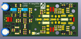
And here's the little 100W version. 120mm x 55mm, so a little larger than my normal 100W class AB lateral MOSFET amp (100 x 50), but really who's counting.
I think this one is really cool.
I think this one is really cool.
Attachments


Pretty cool SuzyJ.
I’ll be tuned in for your verification build.
Heck, I already have SST404’s, LOL!
I’ll be tuned in for your verification build.
Heck, I already have SST404’s, LOL!
You haven't thought of designing a matching four output SMPS have you? It makes sense from an efficiency perspective and a linear supply is starting to get pretty expensive when you need four high current rails.
Yes, parts count is somewhat higher with four rails, but the transformer doesn't need to be that powerful in comparison with a conventional two rail design of the same continuous output power.
Anyway, a four rail SMPS would be a nice-to-have 😉.
Best regards!
Anyway, a four rail SMPS would be a nice-to-have 😉.
Best regards!
Hi Toni,
I think that the class G/H definition in your link doesn't hold true. It's not a matter of how many rails there are, rather than whether the upper one(s) switch the rails or follow the output.
Best regards!
I think that the class G/H definition in your link doesn't hold true. It's not a matter of how many rails there are, rather than whether the upper one(s) switch the rails or follow the output.
Best regards!
We are all right!
E.g.: In this discussion Bob Cordell explained non switched is Class H but in his second edition book non switching as Class G. 😱 But he also adds, that there is a naming confusion between US and Japanese definitions.
Douglas Self in the 6th Edition of APAD adds some more confusion: Class G is switched and/or tracking, Class H is a single voltage system where the inner power transistors have a mostly constant Vce.
This is the reason I call my/DaveZan's design "New Class H".
IMHO: suzyj you can name it Class G or H whatever you like more! 🙂
BR, Toni
Last edited:
When I had windows machines they were junk after about 3 years.
I disagree here , my main system with i7 3770K is going strong since 2013 and it is running Windows 10 now along side XP in dual boot.
8 yrs passed still a very fast system , recently oced the cpu to 4.2Ghz and upgraded ram from 16Gb to 32Gb.
Hi Suzij,Oh bugger! My nomenclature is terrible, and I’ve already ordered PCBs!
nomenclature isn't everything that counts, I think. Even the most prominent authors appear to be discordant regarding the class G and H definitions 😉.
Best regards!
Even the manufacturers don’t agree. The only thing that is certain is that G comes before H in the alphabet, and amplifier classes tend to get labeled in order of appearance. That would make the linear tracker version class G because it was used first and the switched type came later when transistors got faster. And in the (in)famous Carver cube, the mid rails tracked and the uppers switched, which would also follow the same “G before H” logic.
That logic may not follow for RF classes E and F, because E is inverse-F, but does have explicit closed form design equations where F does not. So there is precedent for things being named out of order.
It is good to see this type of thing applied to more “practical” amps that many people can build, rather than just the 4 and 5 kilowatt monsters that only a handful of us would ever use. Some people are afraid of them, claiming poor sound quality. But properly implemented they sound really nice - in normal use indistinguishable from regular AB. Smaller heat sinks, perhaps no fans, for the 200 watt power class is a big plus.
You haven't thought of designing a matching four output SMPS have you? It makes sense from an efficiency perspective and a linear supply is starting to get pretty expensive when you need four high current rails.
I confess to a significant degree of raw fear when it comes to switch-mode supplies. I'm very happy mucking about with all sorts of things _after_ the transformer, but having significant amounts of circuitry that's directly on the mains isn't my idea of fun.
That said, while waiting for boards and parts to arrive to prototype these guys, I'm looking at how I'm going to test them, and the voltages and currents (not to mention the simple number of rails) is just totally incompatible with what I have at home to test gear, so I shall have to start building or buying supplies.
I share your fear Suzy, but if anyone is up to the challenge I think it's you. SMPS's are pretty simple devices these days, there are plenty of good driver chips available that do most of the work. Selecting and quad winding a suitable core would be the hardest part of the job. The mains input wiring is simple but good primary/secondary side isolation is essential.
I'm currently testing a 500W +/-40V Ebay SMPS that I bought to power a quad of your 50W amp modules. They pull the feedback off the primary side so there is no opto providing feedback to the PWM. It's simple and works well enough for a power amp power supply.
If you go linear you'll either need a pair of transformers or have one wound with four secondary windings, which could be expensive. Two bridges and four filter caps adds to the size and cost.
I know you love Mosfet output stages, as I do, but if you are chasing efficiency in this design a BJT output stage does make more sense.
I note you don't even have to wind your own transformers these days...
https://au.mouser.com/Wurth-Elektronik/Power-Transformers/WE-LLCR-Series/_/N-1z0jmj8Z8u9n5Z1yxgvs2
https://au.mouser.com/Wurth-Elektronik/Power-Transformers/WE-LLCR-Series/_/N-1z0jmj8Z8u9n5Z1yxgvs2
Here's a TI reference design that may be of interest.
https://www.ti.com/tool/PMP10375
That makes it even easier.
https://www.ti.com/tool/PMP10375
I note you don't even have to wind your own transformers these days...
That makes it even easier.
Last edited:
....and while I was further mucking around I've gone with 6.35mm spade terminals for the power and speaker connections.
I missed this tidbit of information, thank you! 🙂
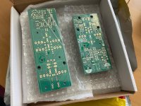
Well, funny you should ask! I’ve given myself a day off tomorrow (helps being the boss, and drowning in TOIL from too many launches), so I might try mixing some of the pine rosin I bought recently with isopropyl and petroleum jelly to see how that goes as flux. Now I have some perfect boards to experiment on.
- Home
- Amplifiers
- Solid State
- A small Class-H Lateral MOSFET amplifier