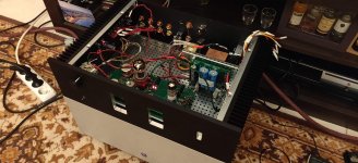
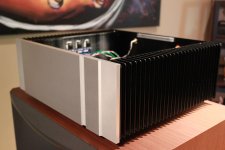
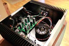
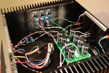
Another successful F4 build, again using some parts that have been sitting on the shelves for 10+ years. These are the Peter Daniel boards with Plitron xfmr. Few building tips:
1 - Don't install capacitors backwards, they blow up!
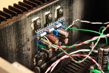
2 - Peter's boards have a separate ground pad for the input that has to be tied back to PS ground, missed that for a few days and could not figure out why it was so noisy on both channels. After grounding, dead silent. Amazing concept!
3 - Ended up at ~6.9k on R9
Thanks again for these great amps.
1 - Don't install capacitors backwards, they blow up!
2 - Peter's boards have a separate ground pad for the input that has to be tied back to PS ground, missed that for a few days and could not figure out why it was so noisy on both channels. After grounding, dead silent. Amazing concept!
3 - Ended up at ~6.9k on R9
Thanks again for these great amps.
Attachments
Hi there,
congrats! Not so lucky here :-(
I replaced r9 with 10k (from 5k)
I resoldered P1. No change
I get 200mv at 40v input from the variac and growing fast. P1 does not do anything, no matter how much i turn it in any direction.
And this in BOTH channels.
P2 impacts dc offset at the speaker posts, normal behaviour.
PSU puts out + and - 25-26v on each side respectively at full 120V from variac.
I do not know where to start debugging.....
Last edited:
Doh...I forgot to populate R8 on both boards🙂 I'm about to.....
Thank you for your attention 🙂
Thank you for your attention 🙂
thank you, very generous of you. I am sure that long reply wouldn't have gone to waste anyway 🙂 As a matter of fact I ran into another potential problem.
I had time to bring up one channel on the variac and the bias now works like a charm, 130mv at start, then went by itself to 195mv or so in about 40 minutes.
Adjusting the dc offset at the speaker posts however did not go as smoothly.
I eventually managed to get it stable at 0.08V, but for a while it would swing wildly from negative to positive and even the high voltage warning sign flashed momentarily on my meter. I do wonder what that is about, it sounds a bit risky for my speakers.
I believe it swung every time I adjusted, even ever so slightly, the 500R trimmer pot, then settled after about 30 seconds. Perhaps it did so while the variac was putting out below 110V, I cannot say.
Thank you in advance for any help.
input shorted, no load
changes during setting are slow-ish
try wiggling/tapping (slightly) trimpots
if that result in voltage spikes, replace them
changes during setting are slow-ish
try wiggling/tapping (slightly) trimpots
if that result in voltage spikes, replace them
Hello, unfortunately I had no luck with my build :-( Here are pictures of the faulty channel, hopefully you can see them:
f4 | Flickr
Everything worked perfectly so I decided to solder R9 properly through the holes on the board and then close off the chassis and enjoy the amp. The 8k resistors were merely riding on the leads of the previous 5k. So I did. And then (fortunately) I ran a last test before closing the box and on the left channel bias was strange, too much too soon, then it went over 1500mv all of a sudden and the fuse blew. I tried everything in my power, resoldered a different 8k, made sure there were no bridges etc. Nothing works, With 60V from the variac and P1 at lowest, bias sits at 160mV and rising fast if I raise the input voltage (from variac). P2 does not seem to have any impact on dc offset, which behaves erratically, going up and down. Bias also sort of fluctuates slightly without any visible cause (not so on the other channel, which seems to work beautifully). I have no idea what to do.... P1 and P2 measure proper, they seem to function) Any help will be greatly appreciated, I 'm sure you can tell!
test mosfets with buzzer, to check for toasted one
if you find one suspicious, lift one side of its source resistor and confirm
when that is sorted, remove TL431, check surrounding components, replace TL431
of course, checking all solder points and possible shorts and no continuity between mosfets and heatsink ......
if you find one suspicious, lift one side of its source resistor and confirm
when that is sorted, remove TL431, check surrounding components, replace TL431
of course, checking all solder points and possible shorts and no continuity between mosfets and heatsink ......
hello and thanks. Which one looks toasted? I measured all resistors on both boards and they measure the same (without desoldering). However all center pins on mosfets on the toasted board have continuity. On the working board only same type of mosfets have continuity on that pin. On top of everything I am a tube person and my SS knowledge and vocabulary are limited. What now?
oh, the center pins are ok, they communicate because that channel was hooked up to the PSU, so I have no information to offer. I tested the mosfets with the buzzer, for continuity (that's what the buzzer means?) and they all seem to behave the same. No contact with the heatsink either
- Home
- Amplifiers
- Pass Labs
- A guide to building the Pass F4 amplifier