The tubes make a lot of difference in the sound because the F4 essentially has no sound of its own... it sounds like whatever drives it.
6L6 - I suppose that is good and bad. I was hoping I would be able to bypass the preamp entirely and drive the F4 straight from my Denefrips Ares II DAC which would let me evaluate the F4 in a purer way. Sadly, the levels from the DAC are a few dB below my normal listening and the Schiit Freya tube stage is my only way of generating enough gain to drive the F4. I have a ton of tubes I can roll into the Freya but it will take time to find the best match.
Hi everyone, I searched the forum for ever and could not find the solution to my basic, yet essential dilemma. What kind of fuse should I use with the F4? The Schurter IEC connector takes 2 of them, I have never seen that before... I read the first watt F4 manual and it says 2.5A slow blow should be used (5x20mm). Is that correct? Times two? Thank you
Yes, the starting fuse in 120VAC countries is 2.5A slow. This needs to be on the Live side.
Use a 10A fast on the Neutral. This will effectively make sure the only fuse is on the Live, and ensure if there is a fault, that the Live blows first.
Make DAMN sure you don't mix them up.
Use a 10A fast on the Neutral. This will effectively make sure the only fuse is on the Live, and ensure if there is a fault, that the Live blows first.
Make DAMN sure you don't mix them up.
Last edited:
6L6 - Is there any reason why you can't have both fuses be 2.5 amp slow blow fuses? That is what I did and it never occurred to me to have a higher amp fuse on the neutral side but now you have me wondering.
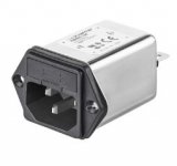
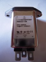
What Schurter IEC socket is that ?
Do you have a picture?
They as std. do take two - but the second position is only for the spare.
You should actually never have two fuses., in fact it is normally prohibited to have fusing on neutral.
Do you have a picture?
They as std. do take two - but the second position is only for the spare.
You should actually never have two fuses., in fact it is normally prohibited to have fusing on neutral.
If you observe the connections on the back of the switch, you should be able to see wether both fuses are active—there would be a connection from the inlet to the fuse and into the chassis per fused line…
agree with Noorgard
Hello members,
Noorgard (#2586) is right. The Schaffner IEC-inlets have two places for the fuses but only one is active, the other is spare (so not connected). You only have to measure resistance from outside pin (hot = p) to inside contact (p=hot). Easy peasy.
The other pins are N=neutral and the lower one PE (in the mid) is for ground/earth (to chassis/case)
Greets
Dirk
Attachments
Hello everyone, I have a question regarding the switching diodes in positions D3 and D4. I hadn't realized I had two types available and I used the 150mA instead of the 200mA version. They're both 1N4148, but the lower amperage one has the suffix TR. Do you think 150mA is enough? Thanks
In europe how do you know which is the live side for the fuse?
Another thing I was wandering is that when you have find the bias should you remove the pots and add resistors in place?
Another thing I was wandering is that when you have find the bias should you remove the pots and add resistors in place?
Maybe you can download IEC standard documents (or manufacturer's datasheets) which tell you which pin of the connector is "L", which pin of the connector is "N", and which pin of the connector is "Protective Earth". Then you can use your ohmmeter to find out which of the fuse trays is connected to "L" and which of the fuse trays is connected to "N".
Best of all, you figured it out all by yourself! You didn't need to pester anybody else for remedial help. Way to go!
Best of all, you figured it out all by yourself! You didn't need to pester anybody else for remedial help. Way to go!
Well, the "Schuko" plugs used in a lot of European countries don't have a polarity.
In the end, it is coincidence which pin ends up live and which neutral.
So you fuse one of those and make sure that your case is directly connected to Protective Earth.
Your protection against shock relies upon blowing the fuse when live connects to PE and draws too much current, or, ideally, if your house has one, the ground fault circuit interrupter / residual current breaker trips.
From experience, the ground fault interrupter ("FI" in German) works very well in such cases 🙂
Regards, Claas
Sorry for the self-quote, but for clarification:
When I wrote "fuse" I don't mean the fuse in the amplifier, because in the case described ("live" has connection to case) that may not even be in circuit, if by chance it ended up in the neutral line, depending on which way the plug was plugged in, or in which way the wall socket was wired (no fixed convention there either), but what will trip in this case is the house circuit breaker for that part of the house wiring.
Therefore, having a ground fault detector / interruptor in your house circuitry is much better, because this one trips much more easily and with much less drama. Nevertheless, you will still sit in the dark 😀
Your protection against shock relies upon blowing the fuse when live connects to PE and draws too much current, ...
Regards, Claas
When I wrote "fuse" I don't mean the fuse in the amplifier, because in the case described ("live" has connection to case) that may not even be in circuit, if by chance it ended up in the neutral line, depending on which way the plug was plugged in, or in which way the wall socket was wired (no fixed convention there either), but what will trip in this case is the house circuit breaker for that part of the house wiring.
Therefore, having a ground fault detector / interruptor in your house circuitry is much better, because this one trips much more easily and with much less drama. Nevertheless, you will still sit in the dark 😀

With the "FI"s (ground fault interruptors / GFCIs / ELCBs), it has gotten very good. When I was a boy, there was a lot of a'sparking and a'arcing 😱 ... now you just notice that somehow suddenly the power is out. 😛
- Home
- Amplifiers
- Pass Labs
- A guide to building the Pass F4 amplifier