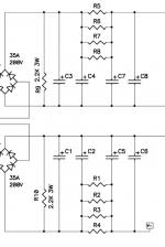
Hello I am trying to recreate it but i see that on the minus supply the R is on the PLUS of the capacitors not on the MINUS as Nelson schematic. Is It right?
Attachments
Last edited:
of course, blame on me
was sorta in hurry and simply forgot few finishing steps when I copied upper to lower half
but you're getting what's important
if needed, say and I'll upload proper (edited) sketch
was sorta in hurry and simply forgot few finishing steps when I copied upper to lower half
but you're getting what's important
if needed, say and I'll upload proper (edited) sketch
No need to redraw! thank you very much!
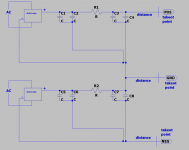
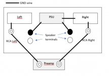
So i am attaching a drawing of the old and new physical design.
The distances are the real ones.
I tried to rotate it as you suggest.
My questions are:
1) Is this what you mean? 🙂
2) You believe it is better to connect the grounds with different wires than on a straight line?
3) You believe that my worst problem on the original design is the T-shape ground that I is too small, I need more distance?
And finally! the case doesn't fit four capacitors in a row! Should i try to fit them in a row?
I try to plan before changing the circuit so excuse me for all this questions!
Attachments
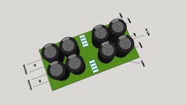
yes for that right pic
organize caps in shape as you can, but wire them according to right picture
organize caps in shape as you can, but wire them according to right picture
Hi nkostop
I will follow your results closely as I have (had) the same issues. I had the issues in my F4, F5 and F5Turbo builds! I have tried all the recommendations I could find in these threads, but for some reason, I couldn’t get it to work. So, I have made 3 alternative solutions you can try or consider. I will however urge you to try Zen Mods solutions first, and please report back if you solve it this way. I owe many thanks to Zen Mod for his great advice.
The 3 alternatives are:
1 Dual Mono PSU.
Connect the ground planes of the 2 PSU’s only through 2 CL-60 thermistors (or similar) to chassis. This worked great for the F5T. Complete silence.
2 Switching PSU.
I’ve used 2 Mean Well HDR 100-24 SMPS’s with great result in the F4. Also, complete silence. This even has the advantage of adjusting the output voltage so you can get 24V at the rails (or even more if you desire). I know using Switch Mode PSU might be a little controversial for some, but I can only recommend it 😉 If you like to add some filtering, to the SMPS them have a look at Mr Pass’ SONY VFET AMPLIFIER Part 1 https://www.diyaudio.com/forums/att...34-diy-sony-vfet-pt-1-a-diy-sony-vfet-pt1-pdf . I do not have any filtering right now.
3 This one is a little tricky, but it worked for my F5 (See illustration).
DISCONNECT the GND to one of the channels (say the left channel) and connect GND on the left channel ONLY through the RCA connector and your connected equipment (preamp, DAC ...). This will break the ground loop, but also leave the channel floating when not connected. This means that you CANNOT use the left channel unless both the left and the right channels are connected to the preamp.
Then connect the GND Speaker terminal of the left channel directly to the PSU GND and NOT to the left channel board.
Adjusting Bias and DC offset can be done while connecting a RCA cable from the right channel RCA to the left channel RCA. This prevents the left channel from floating while adjusting.
Attachments
I know, but it works 😱though, things not exactly proper that way
I tried to connect them as the schematic, no change at all, not better not worst.
Exactly the same.
I am checking with an rca connected between the two inputs if the hum persist.
I also tried to remove ground connection from one rca and the hum is still there.
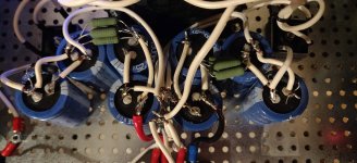
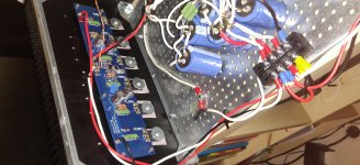
I am attaching a photo of the last arrangement... I know it is a bit messy now.
Maybe use something like a copper bus bar? Know it seems to me like a star ground.
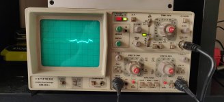
I am also attaching a photo of how it is on the outputs with the speaker connected and the oscilloscope parallel and connected to an iPad on battery.
Exactly the same.
I am checking with an rca connected between the two inputs if the hum persist.
I also tried to remove ground connection from one rca and the hum is still there.
I am attaching a photo of the last arrangement... I know it is a bit messy now.
Maybe use something like a copper bus bar? Know it seems to me like a star ground.
I am also attaching a photo of how it is on the outputs with the speaker connected and the oscilloscope parallel and connected to an iPad on battery.
Attachments
I mean - leave everything as is, and make fat bridge ditto between two pcbs
if nothing else, it'll show is it there potential difference between them
try to see original FW F4 pictures - everything simple, no hum or buzz
if nothing else, it'll show is it there potential difference between them
try to see original FW F4 pictures - everything simple, no hum or buzz
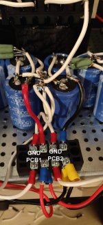
Can you post a pic of that terminal block, curious to see what way the GND from each PCB is connected to the cap bank
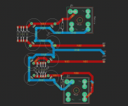
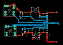
I tried to connect with a fat wire:
1) Gnd of one pcb to other
2) Input ground of one pcb to other
3) Output ground of one pcb to other
Nothing changes at all
I am posting three pictures of how the ground is connected to the pcbs.
1) Gnd of one pcb to other
2) Input ground of one pcb to other
3) Output ground of one pcb to other
Nothing changes at all
I am posting three pictures of how the ground is connected to the pcbs.
Attachments

Just some friendly observations and what I do personally... I like to mount the transformer at the front of the amp, rather than at the back as you have it. My monoblocks have large toroids with steel covers. I tightly twist all rectifier wires, both to and from. I do my best to route twisted input wires and speaker wires far away from any PS components or wiring. DC to pcb's? Ya tightly twist those too. My own caps are screw mount with a custom copper plate but with caps like you are using, I would have used one of the many pcb options you see around here to keep that nice and tidy. Hope you are able to get it figured out, the F4 is one of my favorites for sure..
yup
major reorganization, as W. sez
if nothing else, make PSU pcb - you can do that from raw pcb material, using exacto knife and metal ruler .... 1.5mm drill
major reorganization, as W. sez
if nothing else, make PSU pcb - you can do that from raw pcb material, using exacto knife and metal ruler .... 1.5mm drill
If building a pair of F4 stereo amps, do all 8 FETs have to be matched? I plan to run as balanced monoblocks.
F4 has two sets of (3) devices per circuit board. Three N channel and three P channel.
Those sets of (3) only need to be matched to each other, so one of the mosfets doesn’t turn on early and hog all the current while the other two just loaf along and do little...
So on each PCB the N’s need to match each other, the P’s need to match each other. The N’s and P’s do not need to match. (and will very rarely do anyway...)
They do not need to match between the left and right boards in the chassis.

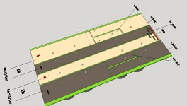
Here is a easy version for a DIY stereo power PCB using basic copper clad board. 🙂
Hope the pics are quite self evident.
The gaps between strips I router clear with a Dremel, but can of course be corroded or even scratched clear. The bridge that connects the two inner strips can just be a piece of wire.
Hope the pics are quite self evident.
The gaps between strips I router clear with a Dremel, but can of course be corroded or even scratched clear. The bridge that connects the two inner strips can just be a piece of wire.
Attachments
- Home
- Amplifiers
- Pass Labs
- A guide to building the Pass F4 amplifier