^ I have been making more boards like that lately. It is pretty simple to do, just a little care with the Dremel tool or Xacto knife is needed. 
First of all thank you everybody for the support!
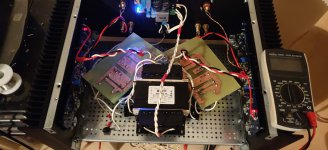
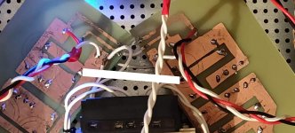
I made two boards the old school and rearrange the setup. Not finished yet.
I cannot believe that I cannot fit everything in such a huge case!😛
So what I did:
1) Two pcbs with the power supplies connected with a small cable on the end for the Grounds
2) Twist cables 220v and 24volts
3) Moved transformer to the front
Have not yet done twisting the bridges wires.
The hum (50hz) is still there. It is much less audible but it is there. The speakers are 96db. It is a difference off course.
It happens only when someting is connected to the amplifier.
I will continue the rearrangement but some suggestions would be great!
Attachments
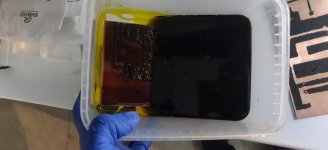

I have etched many a board that way. I make a template on graph paper, tape it to the bottom of the board, drill the holes part way. I then pull the template off the board, take an artist brush with Testors model paint and connect the dots. I then bake it in the oven for a short period of time. After etching I remove the paint and finish drilling the holes. By not drilling the holes all the way through, the board will float face down during the etching process. Heating the ferric chloride speeds up the process. Great for one of a kind boards in a hurry.
This still hums with both inputs shorted together with no other equipment connected? Not saying it will fix anything but remember that there are huge nasty current pulses in those rectifier wires. That puts those high on my twist list. Is your transformer interwind shield connected to the chassis ground point? I personally like that chassis tie point a few inches from the AC inlet ground at the back. I've been getting more interested in these SMPS solutions lately and might start going in that direction in the future. Quality seems to be much better than 10 or 15 years ago.
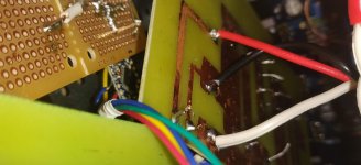
Looking at your latest changes... if someone handed me this amplifier I would add a run (or two) of fat ground wire (because of the long distance here), as indicated on this picture. And don't connect anything else to this added wire. We don't want any of our other grounds "between" those two points directly between those capacitors as you have it now. We need a little distance there where we branch off our "sensitive" grounds to the rest of our circuit. There is current traveling directly between the capacitors we want to stay away from. Not saying this will solve everything, just good practice in general, and something I would do at the start before looking into other potential problems.
Attachments
I will do it william2001 thank you!
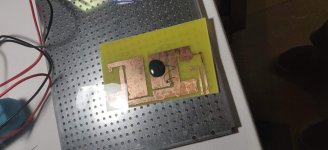
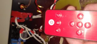
Today I was a little bored on working with the power supply, so I started working on a simple remote control to power on and off the F4, I will extend it to support my preamp and dac (from the same remote).
Is not properly connected just testing. Some photos here and also If anyone is interested I started a thread here Arduino Based Remote Control
I have opensourced the code and I will add more features in the future (I hope!)
I have added sleep mode so the amplifier is always on standby but it consumes less than a milliamp ( sustainable🙂 )
It is fun to be able to open and close the amp from the couch!
Attachments

Hello
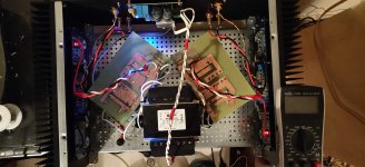
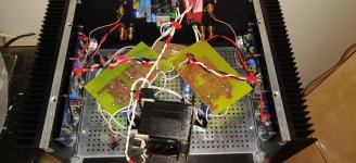
I finally found a way to completely stop the hum....
I drop the transformer on one side and if it is 90 degrees on the side no hum at all...
what does this mean?😕
I am starting to clean the mesh and finalize the inner setup and apply the other comments that you told me!
Thank you all for your support
Attachments
Hey, nice work. I was wondering if it was the transformer but hadn't thought of flipping it like that. Here is something that Nelson had posted awhile back about the toroid's in these amps... found with the search function.
"Originally Posted by Nelson Pass View Post
Something I have always done on FW amps is to rotate the toroid +/-60 deg
in operation, as one position will give minimum noise. Usually there is a
lobe of radiation, and pointing it at (or away) from the right spot is a big help."
"Originally Posted by Nelson Pass View Post
Something I have always done on FW amps is to rotate the toroid +/-60 deg
in operation, as one position will give minimum noise. Usually there is a
lobe of radiation, and pointing it at (or away) from the right spot is a big help."
Pass DIY Addict
Joined 2000
Paid Member
This is good to note and I've run into myself with tube amps I just completed. That EI core transformer has very specific "directionality" to it's magnetic field. Rotating 45 degrees or 90 degrees might be all you need...
Looking at a set of speakers that are 4ohms, the F4 manual states the following...
"it will deliver up to 25 watts into 8 ohms with a damping factor of 40. It will do 50 watts into 4 ohms"
Any real world experiences, or anything changes i should consider doing to the amplifier for a 4ohm load?
"it will deliver up to 25 watts into 8 ohms with a damping factor of 40. It will do 50 watts into 4 ohms"
Any real world experiences, or anything changes i should consider doing to the amplifier for a 4ohm load?
F4 and BA-3 are the amplifiers most suited to running lower-impedance loads. 
Do nothing different, enjoy!
Do nothing different, enjoy!
I completed my build of the F4 today. Everything went well but I've run into some questions when it comes to biasing the amp. After setting the bias across one of the resistors to 130 mv I let it cook for an hour and then reset the bias to their maximum levels. Then I let the amp cook for another hour or so with the lid on. Mosfets and case (4U Chassis) are both around 41 degrees Celsius. I'm getting fairly different readings across the R16-R21 resistors as well as different readings on the left and right side. Those are:
Left Right
R16 200mV 156mV
R17 157mV 167mV
R18 200mV 202mV
R19 180mV 185mV
R20 180mV 175mV
R21 195mV 165mV
Average 185mV 175mV
Offset at speakers on both sides is just 0.4mV and probably tweakable lower.
So several questions.
1) Is the variation on the same side between resistors normal or something to be concerned about?
2) Is the variation between sides something to be worried about?
3) Is my inability to bias to 200mV a problem? If so, is replacing the R9 resistor (currently 10K) with a lower value still the best/only solution? I hate the idea of taking the whole thing apart just to replace one resistor!
3) How does bias affect the sound quality anyhow?
Thanks.
Hi, guys!
Depending on a few undecided factors, I may or may not convert my BA-3 to an F4. For now I have settled on finally finishing my BA-3 to it’s final iteration, whatever that means.
But, should I choose to build an F4 instead, are there any downsides and absolute no-go’s in using 10.14mA matched original Toshiba JFETs? IDSS is a bit high, but perfect for a BA-3. i guess dissipation will increase, of course. So I might sink them woth some TO-92 sinks on hand. But other than that? I know from reading previous posts using higher IDSS is prolly safe for an F4. And since I have scarce originals on hand, I don’t wanna order new ones.
Final decision will be made wrt speaker choice vs gain structure. For now I am settled on BA-3, but this is one of the questions who’s answer might help decide the future.
Thankful for any insight!
Regards,
Andreas
Paul, 1) It would be nice to see some better matching among your devices there. I don't remember what the acceptability cutoff is with that. You've got some devices doing more work than others for sure. 2) see #3 3) You can piggyback R9 from the top with another 10K to get more bias adjustment. Maybe not NASA soldering approved but I think is fine here.. 3) Find Nelson's article "Leaving Class A" for some education about why more bias might be something you could possibly want and desire.... (spoiler - you want lots)
I completed my build of the F4 today. Everything went well but I've run into some questions when it comes to biasing the amp. After setting the bias across one of the resistors to 130 mv I let it cook for an hour and then reset the bias to their maximum levels. Then I let the amp cook for another hour or so with the lid on. Mosfets and case (4U Chassis) are both around 41 degrees Celsius. I'm getting fairly different readings across the R16-R21 resistors as well as different readings on the left and right side. Those are:
Left Right
R16 200mV 156mV
R17 157mV 167mV
R18 200mV 202mV
R19 180mV 185mV
R20 180mV 175mV
R21 195mV 165mV
Average 185mV 175mV
Offset at speakers on both sides is just 0.4mV and probably tweakable lower.
So several questions.
1) Is the variation on the same side between resistors normal or something to be concerned about?
2) Is the variation between sides something to be worried about?
3) Is my inability to bias to 200mV a problem? If so, is replacing the R9 resistor (currently 10K) with a lower value still the best/only solution? I hate the idea of taking the whole thing apart just to replace one resistor!
3) How does bias affect the sound quality anyhow?
Thanks.
I would disassemble everything and group them in proper triplets in each channel (combining between channels)
positions:
R16,17,18
R19,20,21
edit: after more staring at your table, I would just flip positions of mosfets placed in R17LEFT and R18RIGHT
then all is good
take care that uniform thermal arrangement is one of important things here - not too much grease and same torque at all screws
Last edited:
William2001 - Thanks for that suggestion of piggybacking a resistor on R9. That might be easier.
Zen Mod - Switching those two mosfets does look like it would bring the two sides into better balance. If I don't do that what happens when one position has a 20% bias than the other mosfets? Does it impact the sound or just shorten the life of the part?
Zen Mod - Switching those two mosfets does look like it would bring the two sides into better balance. If I don't do that what happens when one position has a 20% bias than the other mosfets? Does it impact the sound or just shorten the life of the part?
mostly more unease rolling in bed, while you're sleeping
if everything else mentioned is OK, you can live with 20% spread (didn't check your calculus), but why not making it in best way you can ......
if everything else mentioned is OK, you can live with 20% spread (didn't check your calculus), but why not making it in best way you can ......
I managed to replace the R9 resistor on the weak side with a 5K which permitted me to get the bias up to an average of close to 200. I didn't want to go higher since I didn't replace the resistor on the left side deeming it close enough for now.
Once I get a chance to listen to the F4 for a while and decide if I like it I'll figure out whether swapping the mosfets and replace the left side R9 is worth doing. I still have a set of Aleph J boards that I may build out and swap into this chassis.
F4 isn't adequately driven by the solid state stage in my Schiit Freya so I am using the tube stage which does have adequate gain. But now I need to evaluate the F4 and how the tubes contribute to the sound which is going to make comparisons to my F5 more challenging.
- Home
- Amplifiers
- Pass Labs
- A guide to building the Pass F4 amplifier