Yes you can do that!
The point where you link the respective +/- of the 2 boards together will become your star ground, at least that's the way I would do it!
EDIT: You don't link across the boards , but link to a common point (star ground) in the center of the 2 separated boards, then all your other ground (from boards/Output posts/ etc. should be routed to that very point as well.
You will find examples of star ground wiring here in the forum as well.
Last edited:
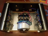
My transformer is quite large which is causing some space issues, is it OK to split the power supply board down the middle. There seem to be no connections in the traces on the boards and I think I would just need to take a wire across on order to connect the two GND.
I would also consider riser panels from the diyaudio store to bring the power supply board on top of the transformer
Riser Panels – diyAudio Store
See examples over there
Splitting the board is an option, however it will probably increase the impedance: ideally you dobt break the board.
See 6l6’s build guides for more details
Does that large transformer happen to have two sets of secondary windings? If so then it could be used in a quasi dual-mono configuration, with a separate PSU board for each channel, each fed from an independent pair of rectifiers.My transformer is quite large which is causing some space issues, is it OK to split the power supply board down the middle. There seem to be no connections in the traces on the boards and I think I would just need to take a wire across on order to connect the two GND.
@ syracuze, I have checked the height and yes a riser board will fit.
@ Tungsten, I,m afraid you've lost me a bit there, below are the specs from Canterbury Windings (if that helps).
The universal power supply board has one of those break lines down the middle it is different from the board used by 6L6 on page one of this thread. The black wire in the 6L6 image goes to the chassis ground bolt and I think that even without splitting my board I would need 2 wires going to chassis ground one from each side .......I think!
Power rating: 756VAPrimary: 0-230V @ 50Hz
Secondaries: 2 x 0-18V @ 21A rms
Regulation: approx 5%
Estimated dimensions: 163mm diameter away from leadouts x 82mm high
Mounting: standard mounting kit (adds approx 4.5mm to the height)
Leadouts: approx 200mm long flexible (stranded)
Audio grade construction
Hi 66deg,
Are you using a chassis with predrilled holes? If so, can you see if there are tapped holes
on the back of the front face plate where you can mount the PS board?
Dennis
Are you using a chassis with predrilled holes? If so, can you see if there are tapped holes
on the back of the front face plate where you can mount the PS board?
Dennis

Toroid Corporation in Maryland USA sells vertical-mount toroid brackets
Toroid Corporation > Products > Mounting & Hardware > Vertical > L-Bracket
Toroid Corporation > Products > Mounting & Hardware > Vertical > L-Bracket
@ Dennis, That would be a great solution, unfortunately, I ordered a black front panel which for some reason can't be made with those holes in.
Thanks for all your replies, I thinking either the vertical mount or the riser panel would be good solutions.
Thanks for all your replies, I thinking either the vertical mount or the riser panel would be good solutions.
Ha. I see we all had the same thoughts. Sorry the thread didn't refresh for me so the last post I saw was your question...
It turned out that vertical would not fit either so I bought a riser board from HiFi 2000 and will fly it over the top of the transformer.
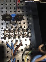
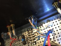
Here are some pics of my 230V primary wiring, from left to right ( in the first image) it goes,
1) Transformer neutral.
2) IEC Neutral.
3) IEC Live.
4) Transformer Live.
Here are some pics of my 230V primary wiring, from left to right ( in the first image) it goes,
1) Transformer neutral.
2) IEC Neutral.
3) IEC Live.
4) Transformer Live.
Attachments
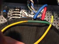
...I have an earth cable out of the transformer...
Connect it directly to the chassis earth point.
All is complete and I'm just waiting for the correct fuses to arrive.
I have one last question (that is if all goes well) to do with the LEDs that I have flown out to the front panel. Do they have to be the same value as the ones on the BOM Mouser part 78-TLHG6400 . I had some blue ones which probably have a different value and used them instead, so I just wanted to check that is ok before switch on.
I have one last question (that is if all goes well) to do with the LEDs that I have flown out to the front panel. Do they have to be the same value as the ones on the BOM Mouser part 78-TLHG6400 . I had some blue ones which probably have a different value and used them instead, so I just wanted to check that is ok before switch on.
any will do
if you have clear ones , start with 22K resistor and go upwards , if they start drilling a hole in your head
if you have clear ones , start with 22K resistor and go upwards , if they start drilling a hole in your head
You don't really need two CL-60, a single one on live will do nicely, I'd remove the one on the neutral side of your terminals and connect your two blue (neutral) wires together.
ZenMod - you live where the mains is 240v, do you have any insight?
ZenMod - you live where the mains is 240v, do you have any insight?
my usual recipe, per channel of any of my Babelfish , practically all FW form factor amps :
250VA donut, two bridges , 33mF-0R1/5W-33mF per rail
always using 10R NTC per Donut, fuse T2A
250VA donut, two bridges , 33mF-0R1/5W-33mF per rail
always using 10R NTC per Donut, fuse T2A
- Home
- Amplifiers
- Pass Labs
- A guide to building the Pass F4 amplifier