to CAL3713
Hello CAL3713,
I had the same problem with 'lead-free' - solder. The solderjoints looked good
but the flow through the holes around the legs of the parts as well the flow to the top (other) side of the pcb wasn't good. And often the trace continues on the other side of the pcb. And if the the solder doesn't flow through - no contact or bad contact.
I will never use 'lead-free' solder for through hole electronic parts anymore!
I've learned this especially in my last build (M2X - especially the inputboards
with SMD-parts - I had to resolder complete boards with good old tin-lead-solder for electronics.
No problems anymore! And it flows...
Greets
Dirk
Since coming back to electronics diy in around 2011, I did almost exclusively use lead-free silver-bearing solder, mostly this one:
LZ FP BF 1,0 100: Soldering wire, lead free, 100-g reel, 1.0 mm, Sn95.8 at reichelt elektronik
When I had a simpler / less powerful soldering iron, I still sometimes used 60/40 leaded solder for some PSU work - very thick copper wire, broad traces and such. Since using my current soldering iron (80W), I don't do that anymore either. I am just using a broader chisel tip and set the iron to 400 Celsius (degrees centigrade).
Normally, I set the iron to 350 Celsius / centigrade, use a fine point tip for small resistors and such, a broader chisel tip for larger components and ones that have to be soldered to ground planes, etc.
And a very fine tip and some magnifying glasses for SMD work (350 C) 😛.
I look to keep my tips always conditioned well using Stannol Tippy
STANNOL TIPPY: Lötspitzenreiniger, CT-1, Pulver, bleifrei, 15 g bei reichelt elektronik
I acknowledge that you have to pay more attention to a clean and good solder joint, and that it takes some time for the solder to flow to the other side of the the trough-hole. I have not damaged a component by applying too much heat in the last ten years, though, and didn't have isues with bad solder joints either.
For less experienced builders, it probably is much safer / easier to get good solder joints using a good 60/40 or 63/37 solder with a good rosin core.
There certainly are a number of lead-free solder types around that are more difficult to solder than the "good old stuff" 😉. I remember when my son and I built a valve guitar amp for him, especially he, but also myself, had a much harder time getting good joints using some Sn 99 / Cu 1 solder 🙄. And that was with much more robust solder joints, because we built the amp using tag boards ... 🙄
But I had really good experiences with the 3.5% silver solder referenced above. And it is not expensive. One 100g spool usually lasts a couple of years ...
Best regards,
Claas
...maybe? It depends on how good a solderer you are.
What solder are you using? Is it lead-free? Might be part of the issue.,,
I'm using the Cardas Quad Eutectic (not lead free) and have been using my iron at 350 degrees. First time soldering circuit boards, so I'm still learning. I think I've got good joints on top, but clearly the solder isn't flowing through the hole. I didn't even realize it should be, so I guess that's a fine place to start on my second attempt. And I'll shore up my good board by soldering the back side as well.
Thanks again for all the help folks.
Have basically been putting solder on the tip, then touching the lead and metal pad of the PCB for two seconds or so until the lead wicks up the solder (using a small chisel tip).
Ok, don't worry about the solder, that's some of the best stuff available anywhere.
I suspect you are suffering from some cold joints. Place the iron against the lead and solder blob on the board, melt it until you can get the iron tip against the PCB itself, (since the solder is now liquid, and then count one Mississippi, and remove the iron.
Do that on all the joints on the PCB that's acting funny.
EDIT - we posted at the same time. 🙂
I'm using the Cardas Quad Eutectic (not lead free) and have been using my iron at 350 degrees. First time soldering circuit boards, so I'm still learning. I think I've got good joints on top, but clearly the solder isn't flowing through the hole. I didn't even realize it should be, so I guess that's a fine place to start on my second attempt. And I'll shore up my good board by soldering the back side as well.
Thanks again for all the help folks.
I used cardas solder as a beginner for my 1st builds and if I could tell my newbie self on thing; it would be NOT to use this solder as a beginner. It takes some work to get it right but once you get the hang of it, it was really good. I destroyed one board on the 1st go around
It wasn't the solder. Sorry.
That's good cause my experience was much different. Glad its simple fix
The Cardas Quad is essentially the perfect solder for through-hole, it has nice flux, melts like butter, flows at a much cooler temperature than most solders, is euctetic, and has silver and copper. It desolders easier than basically everything I've tried.
I've been suggesting new people buy it because it is so easy to work with.
I've been suggesting new people buy it because it is so easy to work with.
The Cardas Quad is essentially the perfect solder for through-hole, it has nice flux, melts like butter, flows at a much cooler temperature than most solders, is euctetic, and has silver and copper. It desolders easier than basically everything I've tried.
I've been suggesting new people buy it because it is so easy to work with.
Yea it took a while for me to get to that point. It wasn't smooth at first. Only till I got used to how it flowed and me getting a new soldering station, did it work really well. The Weller I had wasn't cutting it. Been using it now for that last 2 years and will continue to use it
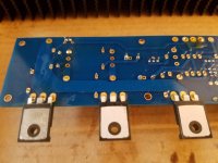
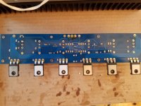
Seems like you all have probably identified the problem, but here are some board pics anyway... perhaps they'll be useful to future builders.
I'm worried about that one mosfet on the end. That's where the resistor smoked and you can see a singe mark on the keratherm.
I'm worried about that one mosfet on the end. That's where the resistor smoked and you can see a singe mark on the keratherm.
Attachments
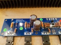
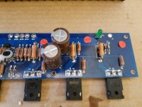

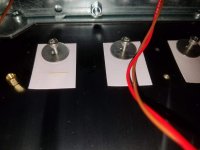
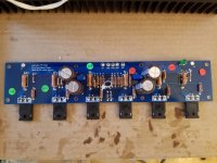
Ohh, and in regards to the mosfet matching, you can see the values associated with each stuck onto the top of the board. Anyone have a good US source that would sell me a matched single if that one is bad? It took 3 weeks I think to get them from Isreal...
This is a great video - YouTube
The trick is getting the iron on the lead and the PCB at the same time, feeding solder into that, and watching the surface tension change (once everything gets to the same temperature) and the solder wick into the hole.
Yeah, and keep feeding solder to the joint for one or two seconds more. That will basically disappear into the hole and build some nice joint the other side as well.
One more thing, about which I'm not sure you (cal) are doing, from your description on how you stuffed your boards: usually, I stick the leads through the holes and solder everything from the underside - let the molten solder wick back through the hole to the top side.
Only the big MOSFETs will be soldered from above - because we tighten them to the heatsink first, and only then solder them to the board, to prevent putting mechanical stress on the solder joint by tightening the bolt on a MOSFET that is already firmly connected to the board.
Regards, Claas
Just did the mosfet test on the suspect looking one (How to Check a MOSFET Using a Digital Multimeter | Homemade Circuit Projects)...
~~~~~~~~~~
1) Set the DMM to the diode range.
2) Keep the mosfet on a dry wooden table on its metal tab, with the printed side facing you and leads pointed towards you.
3) With a screwdriver or meter probe, short the gate and drain pins of the mosfet. This will initially keep the internal capacitance of the device completely discharged.
4) Now Touch the meter black probe to source and the red probe to drain of the device.
5)You should see an "open" circuit indication on the meter.
6) Now keeping the black probe touched to the source, lift the red probe from drain and touch it to the gate of the mosfet momentarily, and bring it back to the drain of the mosfet.
7) This time the meter will show a short circuit (sorry, not short-circuit rather "continuity).
The results from the point 5 and 7 confirms that the mosfet is OK.
Repeat this procedure many times for proper confirmation. That's it, this will confirm your mosfet is alright, and without any problems. Any other form of reading will indicate a faulty mosfet.
For repeating the above procedure each time, you will need to reset the mosfet by shorting the gate and the source leads using meter probe as explained earlier.
~~~~
Unfortunately I get a voltage drop reading (not an open circuit) at step 5. Looks like I need some new N channels (at least).
Ohh, and in regards to the mosfet matching, you can see the values associated with each stuck onto the top of the board. Anyone have a good US source that would sell me a matched single if that one is bad? It took 3 weeks I think to get them from Isreal...
I've got 6 IRFP240s matched at 5.13 you're welcome to have for cost of postage. PM me if interested.
I've got 6 IRFP240s matched at 5.13 you're welcome to have for cost of postage. PM me if interested.
Awesome. PM Sent. Happy to take both N and P mosfets for a single channel if you've got them, just let me know.
What brand and model DMM are you using?
ANENG AN8009 - Autoranging Multimeter Kit, ANENG AN8009 Digital Multimeter Tester with Leads Test Probe AC/DC Voltage Electronic Meter: Amazon.com: Industrial & Scientific
Nothing too fancy, but people seem to like it. The previous model has pretty great ratings.
- Home
- Amplifiers
- Pass Labs
- A guide to building the Pass F4 amplifier