Help
Well, unfortunately I need some help.
I let the amp warm up for an hour. During this time, the right channel bias slowly moved from .13v to .15v. The left channel, however, would start running up, then I'd adjust it back down to match the right. Then it would keep running down. At .11v I moved it back up. I kept playing this game over the course of the hour unti both channels sat steady at .15v (they sat at this value for probably the last 30 minutes).
After the full hour of warmup, I tried to move up to .2v. Every time I adjusted P1 on the left channel it would start drifting in the direction of the adjustment and wouldn't stop until I manually moved it back the other direction. After ping ponging it to .20 and seeing it stay put for a couple minutes I stepped into the kitchen. When I came back two minutes later, it was at 1.xxV and my LED was smoking.
Am currently decompressing on the porch, so I haven't done any diagnostics yet, but would greatly appreciate any input.
I guess maybe the next step is just to fully rebuild that channel and hope my mosfets and jfets survived the blast.
Thanks for any help.
Keep in mind, adjusting the offset causes the bias to drift and changing the bias will cause the offset to drift.
It took me about 2 hours to get my F4 to behave.
Having a second multimeter to monitor offset while adjusting bias is very handy.
It took me about 2 hours to get my F4 to behave.
Having a second multimeter to monitor offset while adjusting bias is very handy.
dont lose hope!
Hey Cal, we've all been there. As a novice myself with a couple builds under his belt, i can recommend walking away from it for a few days. Let it percolate on the back burner. I'm no expert so i leave the troubleshooting to 6L6, ZM and the other jedi's on this amazing forum.
I absolutely recommend 6L6's advice and measure every single resistor prior to stuffing the boards. Don't trust the labels on the bags and don't trust the identifying markings. It takes minutes to do beforehand but hours if there's a problem.
I rebuilt my F5Tv2 countless times before getting everything to work as it should. All the rework contributed to lifted traces, destroyed pads, burned components and loud cursing. I even had to buy the boards and transistors and again from the diy store and start over.
My issues were mostly with tracking down a ground loop. It took a couple of months to finally track it down and it was all worth it.
I just finished an F4 a couple weeks ago and amazingly everything worked the first time. That is not the norm lol.
Driven by a BA-3 driving a pair of franken-La Scalas this is the most transparent amp i've ever heard. Just astounding rock solid imaging in the center of the room. The bass has so much microdetail that other amps miss!
It gets plenty loud for music but for movies i notice the difference in power next to the F5Tv2. I can't wait to build another F4 and run them as monoblocks fed from a balanced BA-3.
Absolutely worth the frustration! Good luck sir!
-Matt
My first builds went easily. Then the F5T. These are different animals. Put it all down to experience. You're learning. Like most of us here.
Re: two fuses. If one is in live and the other in neutral, you have a problem.
Consider a fault to case where the neutral fuse goes but the live does not.....there will still be power on the case, provided that the mains breaker has not blown.
Consider a fault to case where the neutral fuse goes but the live does not.....there will still be power on the case, provided that the mains breaker has not blown.
Put a 10A fuse in the neutral. Or a jumper of wire, but be absolutely sure you are placing it on the neutral side.
Keep in mind, adjusting the offset causes the bias to drift and changing the bias will cause the offset to drift.
It took me about 2 hours to get my F4 to behave.
Having a second multimeter to monitor offset while adjusting bias is very handy.
Thanks. Never got to adjusting offset unfortunately... all of this behavior was simply from adjusting P1.
Put a 10A fuse in the neutral. Or a jumper of wire, but be absolutely sure you are placing it on the neutral side.
Ahh... I had stupidly not even considered soldering inside the fuse box (or putting in a high amperage fuse). Thanks.
Well, unfortunately I need some help.
I let the amp warm up for an hour. During this time, the right channel bias slowly moved from .13v to .15v. The left channel, however, would start running up, then I'd adjust it back down to match the right. Then it would keep running down. At .11v I moved it back up. I kept playing this game over the course of the hour unti both channels sat steady at .15v (they sat at this value for probably the last 30 minutes).
After the full hour of warmup, I tried to move up to .2v. Every time I adjusted P1 on the left channel it would start drifting in the direction of the adjustment and wouldn't stop until I manually moved it back the other direction. After ping ponging it to .20 and seeing it stay put for a couple minutes I stepped into the kitchen. When I came back two minutes later, it was at 1.xxV and my LED was smoking.
Am currently decompressing on the porch, so I haven't done any diagnostics yet, but would greatly appreciate any input.
I guess maybe the next step is just to fully rebuild that channel and hope my mosfets and jfets survived the blast.
Thanks for any help.
Took a quick glance at the amp on my way to work and saw that it wasn't the led that smoked, it was R16, the first 3w .47 ohm resistor.
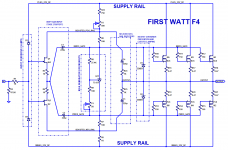
It helped me understand the F4 circuit design better, after I drew the schematic diagram all spread apart, as shown below. In case it helps other members, here you go.
Nelson uses rail boosters in several of his amplifiers, including the "A20" Class-A DIY amplifier, published in 1974 (!). He seems to like them.
Please remember that this amplifier was designed by initials N.P. and not by initials M.J. If you want to ask "why did you do X rather than Y?" be sure to address your question to the correct person.
_
Attachments
Last edited:
It helped me understand the F4 circuit design better, after I drew the schematic diagram all spread apart, as shown below. In case it helps other members, here you go.
Nelson uses rail boosters in several of his amplifiers, including the "A20" Class-A DIY amplifier, published in 1974 (!). He seems to like them.
Please remember that this amplifier was designed by initials N.P. and not by initials M.J. If you want to ask "why did you do X rather than Y?" be sure to address your question to the correct person.
_
Ohh yeah, I need that. Thanks.
And I replaced my burned out resistor, tried the bulb limiter and got a bright bulb. Just ordered a new board and am going to mouser to get a new set of parts. Will just build a complete replacement for that channel.
Am going to cross my fingers and hope that the mosfets and jfets can be salvaged.
How well matched are the mosfets? F4 manual says the MOSFETs in the first watt product are matched Vgs to 0.02v.
Also, check the f5t build thread. At the end I posted a link on how to check your MOSFETs with a dmm.
Also, check the f5t build thread. At the end I posted a link on how to check your MOSFETs with a dmm.
How well matched are the mosfets? F4 manual says the MOSFETs in the first watt product are matched Vgs to 0.02v.
Also, check the f5t build thread. At the end I posted a link on how to check your MOSFETs with a dmm.
I got the MOSFETs from alweit on ebay as recommended somewhere on the thread. I'll check the numbers tomorrow and report back...
Alweit is a good seller and I doubt thats the issue. I'd really like to see some good photos of the back of the PCB.
It's easy to check the matching. Just measure the voltages across the source resistors. They should be the same for each polarity.
Alweit is a good seller and I doubt thats the issue. I'd really like to see some good photos of the back of the PCB.
Should I be soldering both sides of the PCB??
There's not really much happening back there because I soldered everything on top except the caps, the variable resisistors, the JFETS, and the shunt regulator...
Attachments
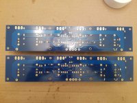
I can take better photos later today after pulling the offending board... (not sure which of those above is actually the bad one)
It's best if the leads of the parts are soldered directly to the traces that are the circuit.
Should I be soldering both sides of the PCB??
...maybe? It depends on how good a solderer you are.
What solder are you using? Is it lead-free? Might be part of the issue.,,
- Home
- Amplifiers
- Pass Labs
- A guide to building the Pass F4 amplifier