Spent the afternoon listening in various combinations. DAC into Coincident 300b Frankensteins with them running my head units and the F4 running the bass. DAC into Franks with the F4 running everything. F4 only. Franks only.
I can't believe I'm saying this, but I might just prefer the F4 by itself. I don't like the bi-amping as much as I thought. Even with the Franks providing the voltage, I still lose some coherency vs. either amplifier on its own. At low volumes, I think the SET has a slight advantage, a little more layering to the sound, perhaps more front to back dimensionality. At high volumes, the F4 stays cleaner. In the end, they're much more similar in sound than I thought possible. And although this is a memory-based comparison, surprisingly, I prefer the F4 to the XA25 I tried earlier in the year... thought the XA25 was a little overly warm, a touch wooly maybe on my speakers.
I do have to max out the volume on my DAC to hit 90db on the F4... but if I end up going that route, I'll just have to add a preamp to my chain.
Should be an interesting weekend of continued comparisons.
And now that everything is up and running, I just wanted to thank the community (and N.P.) for making it possible. This place is an amazing resource and I'm really thankful for all the help. I learned a ton and have a great amplifier.
I can't believe I'm saying this, but I might just prefer the F4 by itself.
Thats not unexpected.
🙂
Thats not unexpected.
🙂
Ha! Very unexpected for me... especially since I've previously pitted the Franks against a SIT2 and XA25. And thanks for all your help in particular!
Well, I made the decision. Guess it's time to start building a second F4 and do the full mono-blocks.
Coincident Frankenstein 300b SET Mono-blocks For Sale - US Audio Mart
Coincident Frankenstein 300b SET Mono-blocks For Sale - US Audio Mart
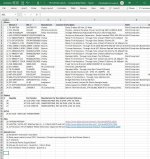
Just purchased the parts for my second F4 & thought I'd post my full BOM in case it helps future builders...
Happy to send the excel spreadsheet too, just PM me.
Stupidly missed one minor component... 20 Keystone Terminal #10 solder lugs (Mouser #: 534-7340, Mfr. #: 7340)
Hi Escucalin,
How did you go with the wirewound resistor? I have left over stock of 0R47 3W, it's Futaba RWS wirewound. Datasheet does not say it's non-inductive so I assume it's slightly inductive. Body size is 1mm longer than Panasonic ERG.
I wonder if the inductance will cause some instability. Any feedback would be appreciated. Thanks.
~Heru
I went for the cheaper part ; and 470mOhm ; they have an inductance in the range of uH hence with no audio range impact.
Hi Escucalin,
How did you go with the wirewound resistor? I have left over stock of 0R47 3W, it's Futaba RWS wirewound. Datasheet does not say it's non-inductive so I assume it's slightly inductive. Body size is 1mm longer than Panasonic ERG.
I wonder if the inductance will cause some instability. Any feedback would be appreciated. Thanks.
~Heru
Hello,
I bought without blinking the wirewound resistors. The inductance in the said resistors is too low to take into account. I was forced to build a home-baked version based on the schematic so i was able to accommodate a larger resistor size.
As one would say in my country ; the resulting effect will be the same as that of the moon light on my porch's rubber shoes (as a explanation: is measurable ... but ... to small to create any perceptible effect).
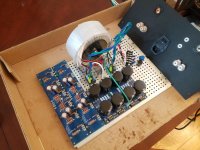
Just waiting for my mosfets to arrive from Israel. Looking forward to hearing the monoblocks...
Also, had one error in my bom, a set of rn65 resistors snuck in there. Once it's all built and I'm sure there aren't any other ingredients missing, I'll repost the corrected bom.
Also, had one error in my bom, a set of rn65 resistors snuck in there. Once it's all built and I'm sure there aren't any other ingredients missing, I'll repost the corrected bom.
Attachments
Just purchased a couple tubes of IRFP9140 and IRFP140 MOSFETs.
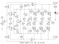
Need to match them. This instructional article says to bias to .2V across the MOSFET source resistor.
Is the actual parallel Source resistance actually .235 Ohm?
What's the actual current each mosfet sees?
What's the total bias for a push-pull F4 channel?
Thanks,
Vince
Need to match them. This instructional article says to bias to .2V across the MOSFET source resistor.
Is the actual parallel Source resistance actually .235 Ohm?
What's the actual current each mosfet sees?
What's the total bias for a push-pull F4 channel?
Thanks,
Vince
there is a whole different world out there ..... on FIRST WATT
always go there for first hand info ...... this here is still second hand one
(second) edit: now I see that Store pcb is having paralleled 0R47 resistors in sources , though - if you observe pcbs , having two on each position (in schematic) is "just" to place two different footprints ...... practically and physically - you still are going to populate just one 0R47 in each source
so , everything applies from my previous post
Last edited:
Ok. The boards I have do use axial or radial, but not both.
Just thought maybe it was an after thought and the .47 ohm resistors needed to be paralleled.
I'm going to match at 24v .5A. That sound like a plan?
Would running the test for 30 minutes be too long or too short to get Vds?
Would like for the heat sink to warm up to operational temp. Maybe 1 hour is better.
Thanks,
Vince
Hi guys,
A couple of noob question.
1. Is it a good idea to put fuse between Vin of each board of F4 and power supply output? If so then what fuse rating to use for bog standard F4?
2. Shared power supply with 40,000uF per rail for bog standard F4, is this sufficient? F4 is driving 4 Ohm speaker (spec says 6 Ohm but measured 4 Ohm with Dmm).
Thanks guys.
Hi guys,
A couple of noob question.
1. Is it a good idea to put fuse between Vin of each board of F4 and power supply output? If so then what fuse rating to use for bog standard F4?
2. Shared power supply with 40,000uF per rail for bog standard F4, is this sufficient? F4 is driving 4 Ohm speaker (spec says 6 Ohm but measured 4 Ohm with Dmm).
Thanks guys.
2) 40 000 is rather low. See a coherent explanation about capacitance here : http://www.firstwatt.com/pdf/art_power_supplies.pdf
Your speakers may be correctly rated at 6 ohm impedance(a coil behaves differently when exposed to alternate current Electrical impedance); - Wikipedia what you measured was DC resistance.
1) A fuse there won't protect much, to put it into perspective :
In the time any wire fuse is blown, any transistors die a few times over.
Last edited:
Test for 10 seconds. Any longer and the temp change will mess up the readings.
Thank Jim. Makes life easier as well.
- Home
- Amplifiers
- Pass Labs
- A guide to building the Pass F4 amplifier