Now it is clear for me why you dont reach highs. I think that at this point the patent is right: the hinges, at top and bottom are a must, because the coil is not stressed that much from the forces that creates the cilinders when bonded and keeped together in the gap, and moves more easily when you make cuts insyde the free space in the coil and in theyr lateralls, as this way we also reduce the coils mass.yesterday i build a mini version of the ruba, measuring 21 cm high, exact an A4 paper sheet. coil is around 3.4Ohm, DC. i used translucent transfer paper. 125grams. but it only reaches to 13Khz
When i remove the leftover paper on the backside that is only there to be able to use the rubber bands. it goes to 14khz-14.5khz. (i leave the top and bottom to still be able to use the rubber bands.)
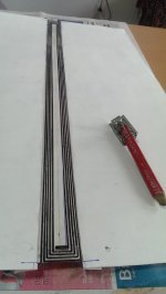
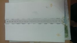
Be aware Wrine, the patent says, and the french guys from the other forum tested this: there can be cuts inside and outside of the coil but they percentage must be between 10 to 50% of the total mass of one sheet of paper (one cilinder-- and no more or less per cilinder) it has been tested that above 20% really has effects on the overall sound. I have now 23% removed now. It seems that the internall cuts lowers the internal mass this way improves the frecvency responce and the externall cuts somehow not only that lowers the coil mass but they also cuts or limits and improves the ruban frecvency response. Look at my pic bellow.
I'll tell you another aspect that i read not only from the patents, but also tested by the french guys, wich is the distance between the external cuts and the edges of the coil: it was found that 2 mm are optimum for getting best from both worlds (mids and hights), and there should be alligned with the hinges; and where the hinges are (top and bottom) there must be no paper at all on the 3cm width of the coil top and bottom (even one or two mm in plus are not good).
Another aspect that i want to ask from you Wrine: friday at the first listening tests that i conducted with my wife, i tryied to listen to the sound that is coming from inside the cilinders. To be honest i hoped to hear some hights from inside because i have seen in pics on the web that others reflect the sound thats coming from there twoo, BUT I COULDNT HERE A THING. My assumtion is that eyther the cilinders are well damped
(and there will be no sound) or there is no sound inside (or the sound coming from the inside the cilinder has lower dB than outside and its perceived as none) or my ear does not perceive them at all. Can you measure this aspect and please tell me what is the real truth?
Thanks in advance.
Cheers
Sergiu
Attachments

ok well you membrane is 225 grams m2, mine is 125 and also used 75 today. so cutting a few pieces near the coil as i already tried does not work(for me) i already cutted in te middle of the coil without any result. the lighter membrane does go a bit higher but what the biggest problem is , (and i again thought i give it another go) is the weird dispersion witch results in dips and peaks. the geometry of the transducer does not allow for a smooth top end.
let me try to explain. (my theorie)
you got 2 cylinders that produce a fullrange signal, but most of the high frequency's emit from center(or at least near the center) now the problem is that these 2 cylinders have an arc that measures around 2 cm from front to where both circles meet and is connected to the coil. when frequency of around 7.5 Khz are played you get a dip and a small peak. when you move your mic a little bit out of the center (so of axis) the frequency of the dip starts moving. its like having 2 tweeters at different distance getting the same signal. problem is at frequency with half the wavelength that is the same as the distance of these 2 tweeters there will be a dip since the wave is out of phase with one another. when you move the measuring mic only a few centimeters you get a complete different graph. with less of a dip or a dip at a different frequency.
when you would remove one of these cylinders at the front side the phase issues are still there be it far less. it also extends to 20khz. the low end will suffer though.
picture
Blue = 2 circle (normal distance from front to where both circles meet, to the coil, approx 2.2 cm) witch comes close to the problem at 7.8 Khz
Green = Single circle measured at 45 degree since this is where the highs are correct , but normally there is another circle in the way.
It is annoying that these dips and peaks shift when you move your head. because in this way a simple dsp would not solve it, or only for one particular position. a lighter coil wont solve this problem either 🙁
I might try a far field measurement to see if the problem blends away 🙂 hopefully
Attachments

Last edited:
Now it is clear for me why you dont reach highs. I think that at this point the patent is right: the hinges, at top and bottom are a must, because the coil is not stressed that much from the forces that creates the cilinders when bonded and keeped together in the gap, and moves more easily when you make cuts insyde the free space in the coil and in theyr lateralls, as this way we also reduce the coils mass.
Be aware Wrine, the patent says, and the french guys from the other forum tested this: there can be cuts inside and outside of the coil but they percentage must be between 10 to 50% of the total mass of one sheet of paper (one cilinder-- and no more or less per cilinder) it has been tested that above 20% really has effects on the overall sound. I have now 23% removed now. It seems that the internall cuts lowers the internal mass this way improves the frecvency responce and the externall cuts somehow not only that lowers the coil mass but they also cuts or limits and improves the ruban frecvency response. Look at my pic bellow.
I'll tell you another aspect that i read not only from the patents, but also tested by the french guys, wich is the distance between the external cuts and the edges of the coil: it was found that 2 mm are optimum for getting best from both worlds (mids and hights), and there should be alligned with the hinges; and where the hinges are (top and bottom) there must be no paper at all on the 3cm width of the coil top and bottom (even one or two mm in plus are not good).
Another aspect that i want to ask from you Wrine: friday at the first listening tests that i conducted with my wife, i tryied to listen to the sound that is coming from inside the cilinders. To be honest i hoped to hear some hights from inside because i have seen in pics on the web that others reflect the sound thats coming from there twoo, BUT I COULDNT HERE A THING. My assumtion is that eyther the cilinders are well damped
(and there will be no sound) or there is no sound inside (or the sound coming from the inside the cilinder has lower dB than outside and its perceived as none) or my ear does not perceive them at all. Can you measure this aspect and please tell me what is the real truth?
Thanks in advance.
Cheers
Sergiu
there is sound coming from the inside. most lower end will be swamped because of the out of phase material but mid and high freq you can hear. i always had reflection in the measurement of the back cylinder, thats why i removed it. only good reason to do use it is symmetry
Hi Ondesx,
9 ohms from 5 turns
Sergiu
F=BIL - 17 turns/5 turns thus with few turns your force is more than 3 times weaker...
F=ma - a=F/m for a mass 3 times heavier you may have the same acceleration if you have a three times higher force...
F=BIL - 17 turns/5 turns thus with few turns your force is more than 3 times weaker...
F=ma - a=F/m for a mass 3 times heavier you may have the same acceleration if you have a three times higher force...
Hi Ondesx,
I am not an expert in this field and i dont understand what those calculations mean. Could you explain or give an example or give me a link?
Cold thinking, this is my thinking: in december i dissasembled a 15inch paper surround speakers for revinding and the burned coil from one pcs was only 3grams. Considering that the coil is new (with the isolation intact) the total mass is 3,2 grams at 8 ohm in 100w sinus (real wattage).
I have 3.4 grams at 8ohms (5turns of Al traces). If you do a coil made of copper wire for the ruban you have 3,2grams. Leaving aside the fact that with the copper wire you lose hight frecv you have the same mass as i have, why do you say that i loose force?
Thanks in advance.
Cheers
Sergiu
Thanks for the explanation Wrine,
I cant wait for the mic to arrive today so that we can measure and compare. An interesting question is how do we measure it? What charts and conclusions should we take? It sounds really good but what influences what aspect?
On the french site those guys only measure the linearised frecv between 250 to 6khz to see how much dB it outputs and they say something about where should we put the mic to really measure it but i forgoted... I remember vague that you can only measure the spl from 1m but for all the frecv responce the "1meter" distance increses but i forgot about what is this distance and how to.. i have to reread all that thread but its on french and has almost 120 pages..🙁
Ps: Wrine i have buyed the Behringer mic. The umic was almost 120 euro and another 89 euro shipping......🙁
This behringer has only xlr conector. Do you know any adaptor to usb?
Cheers
Sergiu
Hi Ondesx,
I am not an expert in this field and i dont understand what those calculations mean.
Cheers
Sergiu
Well, the force of the motor is proportional to the length L of the conductor in the magnetic field. Thus, the greater L, the higher the force. For a given size of the motor, say 0.5m, if you use 5 turns the force is 3 times weaker than if you use 15 turns, because 2.5 m is 3 times less then 7.5m. The diameter of wire or width of the tracks is vey important for the current flowing in the coil, and this is a second factor of the force achieved by your coil.
In few words for a given magnetic field imposed by your construction and geometry, the force generated by your motor is proportional to the length and the current used in your voice coil.
Hope this helps…
Thanks. This clarifyies abit the situation.
i doubt if it need any powering since its based on a panasonic capsule, if it does need phantom power you need some separate phantom power (48v) or a mic amplifier. with phantom, what does the brochure say ?
measurements would be usefull at 1 meter on axis, i understand why they dont measure the full spectrum since it is gone be shark teeth 🙁
yes you could measure a bit further away you will see the low end drop some more. but lets say at 3 meter you are measuring the rubanoide in the room. for quick stuf just to see what happens i measure more up close, you dont want to bother the neighbors with sweeps all day. then after fidling i measure it from a meter. i first put out a 1khz since and measure on my multimeter to 2.85 volt as a reference. i dont have a dB meter so real life dB is unknown for me. even if the mic is calibrated it is all about the rest of the settings in the chain.
Thanks Wrine,
It seems that i need a phantom supply here. Do you know any cheap solution to use something else (not phantom) and conect it somehow to a mic input plug from a pc?
Thanks
It seems that i need a phantom supply here. Do you know any cheap solution to use something else (not phantom) and conect it somehow to a mic input plug from a pc?
Thanks
Thanks Wrine,
It seems that i need a phantom supply here. Do you know any cheap solution to use something else (not phantom) and conect it somehow to a mic input plug from a pc?
Thanks
hmm no not really, best way is using for instance a cheap pre amp. or using something like an digidesign Mbox 1 or 2. i bought an mbox 2 for 30 euro, im not sure yet how they measure, but it is easy to check with a foldback loop. thats why i told you about the umik it has a preamp build in hence it is calibrated to that pre amp. if i remember correct i only payed 100 euro including shipping. there is a german company that sells them to, might be way cheaper then sending it from US.
well i am not really into electronics 🙁 as long as you get 48 volt if it uses phantom power. be sure to check the pins before screwing the mic up. and be sure you have to use phantom. 🙂 looking forward to some measurements. to see if i am completely mental or just being a purist on the freq response 🙂 if the last is true i am happy to be so 🙂. just curious about your results feeling lonely in this topic(as of now) feed me some information 🙂
i bet there is a complete schematic on phantom power on google. i am sure!
i bet there is a complete schematic on phantom power on google. i am sure!
Wrine look what i discovered today about the ruban. The second ruban that i finished today and listened to it sounds flat, no resolution with very few hights and the sound seems to come more from the center not like the ruban from the other days... The prototype that i tought it was nirvana, from friday night sounded extraordinarily good and i can say this with the hand on my heart.
I had to found out why so when i took the membranes from the other ruban (first one) i discovered why: on the newer version i surrounded the coil with super glue and putted some dots of super glue in the center of the coil between the cuts from inside the coil; on the first version from friday night (nirvana 😀) i have puted super glue only on the leteralls of the coil and the hinges zone and NOT inside the coil neither top neither bottom. The rest of the coil have laqueur on it.
Now this newer version lack resolution, lacks finess, naturaless and a big portion of hights wich is very noticeable(like our colleague who made the cilinders from carbon fiber=that's exactly the sound that i get now)...
Have you tried this theory? Both me and my wife have exactly the same impression.
Please tell me you impresion.
Tomorrow i will assemble the other ruban for the other chanell so i can compare directly and faster.
Cheers
Sergiu
well i am not really into electronics 🙁 as long as you get 48 volt if it uses phantom power. be sure to check the pins before screwing the mic up. and be sure you have to use phantom. 🙂 looking forward to some measurements. to see if i am completely mental or just being a purist on the freq response 🙂 if the last is true i am happy to be so 🙂. just curious about your results feeling lonely in this topic(as of now) feed me some information 🙂
i bet there is a complete schematic on phantom power on google. i am sure!
Thank you very much. I was writing my first impressions for this day.
It seems that others dont want to risk some money here, in this project and the ones that finished it dont want to share with us their impressions (SHAME ON YOU GUYS!).
BUT no probs we will take it slow and finish it some day.
I will be testing and probing and happy to collaborate with with you Wrine in this project.
Cheers
Sergiu
well the reason why people dont come back on it is usually an indication of, they dont give a poo 🙂 witch is ok of course. or they dont like sharing 🙂 i love sharing 🙂 mostly my misfortunes but hell its something 😉
About your findings it is quite hard to understand where you had glue and where you did not. here i got a picture of a coil could you play in paint and let us know what you did in 1st and second ? just crude paintbrush 🙂
Btw i thought of a remedy for the soldering question if i really want to use a aluminium coil (and i think the end coil should be aluminum) use thick thick aluminium tape of around 100mm wide or wider if possble. and print the coil and its leads that you can stuck onto the cylinders. the leads will end up near where the cylinder is fastened, from there it is easy to press fit copper on it or use a clamp. this was there is no resonance from the lead wires and you got a complete alumnium coil without a crappy joint inside the paper 🙂 although i like the chemical tinning idear better 🙂 but that should be tested and i ran out of money to spend on these kind of ideas 🙂
when rethinking for your massive version its not an option since its bigger then an A4 paper. for mine it is plausible, tinning the coil is still al option for yours. it also helps prevent corrosion(aluminium does corrode away)
Attachments

Last edited:
BTW one thing is hard to tell since you opted to use every patent in the book 🙂 is where stuff works and where it does not work. i would be happy to send you some coils when you got your mic sorted out. because of this.
I cant test all options alone, and if we for our self want to be clear what works and does not work should test it. when you use every trick at once you wont be able to tell what works and what does not work at all. and i bet there are quite a few of these patents that just not justify the effort.
For me for instance cutting holes int he middle part between the 2 rows of traces did not results in more high freq but less. cutting of the backside did work, cutting of the remaining 1 cm of paper that was still being there doing nothing resulted in another 1.5 khz . i think the trick is it has to be really really rigged from coil to the arc's since this is how it transports the high's to the rest of the membrane, the more you cut in it the less rigid it is gone be. i can imagine where you cut the pieces out in the front next to the coil need some sort of reinforcement just so you did lose weight but increase rigidness as well.
i am still wondering if i should travel to amsterdam and get my 1mm foamboard. its is extremely rigid(compared to papper), and pretty light. but 1 mm thick so i could only use one board for the coil, and glue the 2 cylinders on the edge (my gap is only 3mm in this setup, making a sandwich of 3 pieces 3mm total would be pushing tolerances 😉 )
Btw another options besides foamboard is Depron. look it up if you want , it is used in RC planes. being light and rigid. XPS is another option. but ussualy comes in thick plates. i usewd this to cut moulds on my cnc for concrete, cool stuff
Last edited:
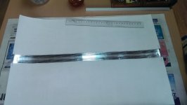
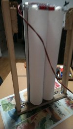
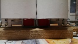
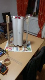
Hi Wrine here is what i finished and listened to all day. In the next post i will show you exactly on one of the first ruban cilinder how i sticked the coil.
I closed the pc my friend so i cannot draw, because of the lousy 7 vents of 120 mm wich i hate. I think that my next pc will be for shure all passive. I dont mind lower performance...
Anyway, enought of the pc. Here it is. This time it really pissed me off, this ruban had perfectly centered coil and exactly 4,5 cm half diam hight each cilinder. Nothing rubs whatsoever, and the cilinders are perfectly alligned, the coil is just perfect, no cuts no patches or stiches only the super glue trycked me...
Here it is.
Attachments

looking good !, one thing the hinges. i really have no clue what they would do what the string could not? the hinges in the patent are for a tweeter. and are clearly there for production purposes. at least i believe. have you ever tried holding the coil with your hands? the high frequency wont change, only the lower if you really force it to stay in the same position. in the tweeter design they just glue those hinges to the structure, no rubber bands needed. it saves money. fiddling around with the bands 🙂
my speaker have sometimes a excusrion of 1 -3 mm playing fullrange, the hinges would not allow this.
my speaker have sometimes a excusrion of 1 -3 mm playing fullrange, the hinges would not allow this.
- Home
- Loudspeakers
- Planars & Exotics
- A DIY Ribbon Speaker of a different Kind