Hello everyone, I am pleased that the topic alive. I sit and re-read the topic, almost learned English))) Guys please give a detailed drawing of a small rubanoida, I would have ordered is ordered turner magnets and make your drawings on blank metal.is focused on the Chinese Neo magnets like these (http://ru.aliexpress.com/item/2-pcs...-Neodymium-Permanent-Magnets/32533395428.html there are 100 x 10 x 10 mm and there is 100 x 20 x 10 mm.I certainly do not trust the Chinese, can you guys send me a normal magnets?We need a drawing and assembly principle with photos or video, not to be mistaken.Prompt what metal ouchshe use? Can it be the exact name.Well, maybe somebody will agree to a fee to make me a trial rubanoida or send me all the parts for its manufacture?I would be grateful, respectful, Vladimir
Last edited:
Hi Vladimir,
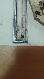
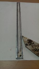
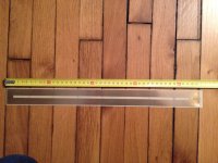
You will need 40*20*10 neodim magnets. Please read the thread again. The magnet issue has been discussed here as well as the steel. You will need AISI 1017 or 1018 or cold rolled steel bars, half a meter long, 30mm wide (original) or 40mm as i did (i wanted a 3mm gap) and 10mm thickness. With 40mm width you will loose some field force but will regain it by making the gap smaller.
Wrine i'm sorry for your printer my friend. Hope it will work better with the ink cartrige repaired and filled.
Cheers
Sergiu
Ps: today i managed to solder the stupid Al coil. Bellow are some pics... You can see that i almost ruined it. 🙂
Attachments
Thank you very much. I read about magnets and about the metal, but I just wanted to ask in the end who is using. Magnets and metal I can find, the assembly drawing have somebody with exact dimensions? What else is required for rubanoide? Coil hope I will make and sell Wrine.
Hi Vladimir,
You will need 40*20*10 neodim magnets. Please read the thread again. The magnet issue has been discussed here as well as the steel. You will need AISI 1017 or 1018 or cold rolled steel bars, half a meter long, 30mm wide (original) or 40mm as i did (i wanted a 3mm gap) and 10mm thickness. With 40mm width you will loose some field force but will regain it by making the gap smaller.
Wrine i'm sorry for your printer my friend. Hope it will work better with the ink cartrige repaired and filled.
Cheers
Sergiu
Ps: today i managed to solder the stupid Al coil. Bellow are some pics... You can see that i almost ruined it. 🙂
If you use the flux and soldertin I linked to you can make nice solderings.
A vary thin coating of flux on the aluminum and soldertin on the tip of the iron.
Attachments
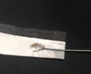
Thank you very much. The soldering needs to be flatter in my case, thats why you dont see so many solder on the joint.
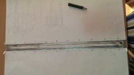
I unsoldered the wires from the coil to make the cuts.
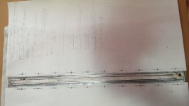
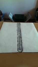
So here we are. Summing aprox 17~18 % of the total membrane surface. Now i have to cut the other half an the bond them together. I also aded hinges, and alligned all the cuts with them.
These cuts lowered the center mass and are calculated at precise locations as the patents says..
As the Lineaum patents says, from they're tests i should gain aprox 3 to 4dB in the upper register 12 to 24khz (to 20khz in my case i hope), dampen some spikes and extend the hights further.
I dont have a mic yet but so i think i will compare them with my 91dB 19khz tweeters from my closed bafle speakers that i have.
Cheers
Sergiu
Attachments
Last edited:
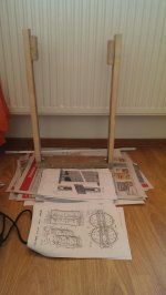
nice work sergiu, in my test, making holes outside the coil did not help at all 🙁, inside i did not meassure anything either to be honest. but because measuring is quite hard with these beasts. it might be my fault. well i went to the store that should sell 1 mm foam board........ guess what...........i called them to ask if they got it in stock and they said yes. then i took a trip to the store took me 50 minutes. to discover they dont have it and they never had 1mm........ they never had it in stock and they never heard of it. then they looked it up on there website(and it was there on the site). and they will call me back tomorow if there distributer can deliver it, since weird enough today 2 people already asked for it 🙂
aaah well i bought some otheer fun stuff, papers and such 🙂
sorry for all the gramatic and typo errors.. i am typing this on a frends pc and i really cant use his keyboard and im kind of having a long night 😉 (super expensive mechanical keyboard that sucks), and his gramatic correction does not work either
sleep well 🙂
Last edited:
well at elast they ordered the 1mm foam board and should be there this week. hopefully i can get a few somewhere this month.
Hi all,
I have some VC if some of you are interested let me know.
nice one 🙂 whats the trace thickness total resistance and the space distance if i may ask? looks like a prety amount of turns.
did you also etched them yourself?
they look nice
well at elast they ordered the 1mm foam board and should be there this week. hopefully i can get a few somewhere this month.
Hi Wrine,
Thanks for the encouragements. No prob for bad english, same here.
Does the foam look like the double adhesive type atached bellow?
Does it have copper on it? How will you etch it?
Attachments

Hi all,
I have some VC if some of you are interested let me know.
Hi Ondesx,
That looks pretty impressive. Can you give some dimensions, impedance? Do you have double sided flexible pcbs?
Thanks in advance.
Cheers
Sergiu
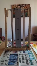
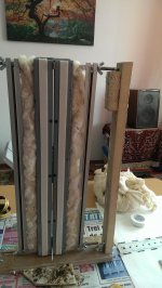
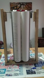
Well, yesterday i waited for the glue to dry, made a frame and today i'm preparing the final assembly. Here is some work in progress. I have only to add some internall damping and then the membrane.
Note: you can observe from the pics that the quality of the paper used is not so good and the frame looks fragile. It is so because this is only for tests. I have the rest of aprox 15meters of 120g/sqm canson paper in good condition in the closet and will make better frame for the finall version.
Cheers
Sergiu
Attachments

Well, yesterday i waited for the glue to dry, made a frame and today i'm preparing the final assembly. Here is some work in progress. I have only to add some internall damping and then the membrane.
Note: you can observe from the pics that the quality of the paper used is not so good and the frame looks fragile. It is so because this is only for tests. I have the rest of aprox 15meters of 120g/sqm canson paper in good condition in the closet and will make better frame for the finall version.
Cheers
Sergiu
aaah well you can always redo it 🙂 so today is gone be the, i got sound day 🙂 have fun fidling around today !!!! biggest cullpit will be the coil i guess. but as mentioned, apparently there are at least 2 people here that make them 🙂 i hope you can get soem sound out of them today and close the day with a smile and a beer 🙂 (and some music)
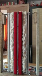
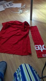
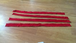
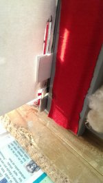
Well i just finished the internal dampening for just one speaker... It tooked me some time because needed some slim and fine 100%cotton material for the metal plates. Fortunate for me i found a nice red 100% cotton Tshirt of my wife (unfortunate for her!!)..🙂) This is original diy, right here. Hope she will not be mad on me. I hope i will finish in time till she comes home. 😀
Cheers
Sergiu
Cheers
Sergiu
Attachments
Thanks Wrine. I hope the same.
Cheers
Sergiu
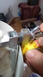
Disaster strikes. I just cut the coil... 🙂))..
Furtunate for me it was a easy fix. The consequences: lost an hour and aded some mass at the bottom of the coil. Lucky am i that this coil is just for tests.
Other things have changed like shrinking the membrane to make a round circle at the top of the cilinders. You know what i mean Wrine. for others i will post some pics after centering. Old dim where 52*50 cm, and now i have 51,5*34cm per paper sheet (perfect dim for 50cm ruban).
Cheers
Sergiu
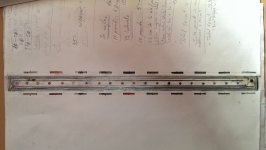
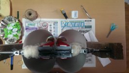
Centering the coil:
As Lineaum ssid in theyr patents, the hinges for lowering the center mass also helps you allign the membrane and the coil in the gap. The hinges will keep the coil in the gap and the membrane will not depend 100% in the elastics. The elastics will just keep the membrane suspended without interfering too much with the coil in the gap. The adenum of the hinges also helps reducing the overall distorsion, improve the frecv response and add some gain (thats what the patent sais).Peace of cake. Draw some verical lignes (1mm from the edge of the coil, to outside) as you see in my pics from bottom to top, this will help when centering the coil in a maner that you will see when its in the gap or out.
First step is to add the plastic stick (these are plastic sticks wich you use to clean your ears from wax) at the boton of the membrane. Second add the wraped paper "like nails" as you see in my pics, then center the membrane, and look at the vertical lines that i told you earlier to keep the coil in the gap, then glue the hinges, then stick them to the metal plates.
Attachments

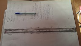
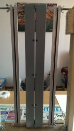
From the pics bellow you can see clearly the "circle" cilinder shape from the top that i was talking about in the earlier post.
In the other pics you can see how the paper from the membranes is hold toghether and alligned.
Cheers
Sergiu
In the other pics you can see how the paper from the membranes is hold toghether and alligned.
Cheers
Sergiu
Attachments
- Home
- Loudspeakers
- Planars & Exotics
- A DIY Ribbon Speaker of a different Kind