You are right but how do you cancel the noise and reflections picked up from the room?Distortion you can measure up close ,frequency response would be at least 50 cm since some phasing would not show up otherwise . A combination would be best but anyhow looking good !!! I just bought some new foam for a big one 🙂 60 cm instead of the curently used 20cm . I hope the low end will improve below 300 🙂
Yeah, i forgot that the increased hight increases lows also, but a gigher inpedance coil helps the speaker reproduce those lows better.
I cant wait to see your results.
Cheers
Sergiu
Hello my friend, how is it going? Did you assemble the bigger motor for the ruban?
Cheers
Sergiu
Cheers
Sergiu
Not yet I have trouble getting the foam formed. I did notice very heavy paper will do to , so a light coil former with like 1mm of of the start of the cylinder where they meet . Then the heavy paper sticked to it. The paper is like 250 grams or something.
I realy should make the big motor to see what happens. What I did test was this
I made a motor that does not have spacers between the bars I threaded the steel so you Suspend them to the side supports(where you clamp the paper) with an stainless steel threaded rod in this way you can make the coil bigger then the motor so you can move the turning point of the coil outside the gap so less movement in directions you don't want and the oportunity to put all the force of the magnets where it belongs in the vertical traces and not the horizontal. Another benefit is you can adjust the gap on the fly by the 4 rods ( made 2 aluminium bracket that hold the 2 steel bars and the magnets in between in the top and one at the bottom)
Because the bars magnetic field, the 2 sides attract each other so they sort of hover in the air only fastened from the side by the rods.
It is much saver to construct then sliding them together with something in between. It is also much much more work.
I'll try the old method for test (with big membrane) with the old method since it is less work and the magnets are weaker 🙂 I'll post a picture of the construction of the above tomorrow 🙂
Interesting my friend. Cant wait to see your adjustible motor.
I just finished the paper preparations for my final coils. Will make the membranes soon.
Till then i disassembled the rubans to spray primer on the bars, add dumping, cut some new longer Al square pipes, add more glue to the magnets etc...
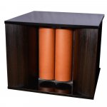
Take a look how the new rubabas 2 looks. It does differ from the first one wich had flat membranes like your first fullrange attempts my friend.
The ideea is interesting and the results:
"Freq: 15Hz to 600Hz
Over 96dB/w/m efficiency
Resonnance frequency at 10 Hz, which is quite unique , as one octave below 20 Hz
Impedance 8 ohms
...."
The most interesting thing is that if you look closely at magnetic motor you can observe how small it seems and how huuuge the membranes are.
ps: the images are proprety of audio consulting's site and are not for making a bad image on their products or for publicity. They are pasted here just for informative and study purpose (of new things) .
I just finished the paper preparations for my final coils. Will make the membranes soon.
Till then i disassembled the rubans to spray primer on the bars, add dumping, cut some new longer Al square pipes, add more glue to the magnets etc...
Take a look how the new rubabas 2 looks. It does differ from the first one wich had flat membranes like your first fullrange attempts my friend.
The ideea is interesting and the results:
"Freq: 15Hz to 600Hz
Over 96dB/w/m efficiency
Resonnance frequency at 10 Hz, which is quite unique , as one octave below 20 Hz
Impedance 8 ohms
...."
The most interesting thing is that if you look closely at magnetic motor you can observe how small it seems and how huuuge the membranes are.
ps: the images are proprety of audio consulting's site and are not for making a bad image on their products or for publicity. They are pasted here just for informative and study purpose (of new things) .
Attachments
Interesting my friend. Cant wait to see your adjustible motor.
I just finished the paper preparations for my final coils. Will make the membranes soon.
Till then i disassembled the rubans to spray primer on the bars, add dumping, cut some new longer Al square pipes, add more glue to the magnets etc...
Take a look how the new rubabas 2 looks. It does differ from the first one wich had flat membranes like your first fullrange attempts my friend.
The ideea is interesting and the results:
"Freq: 15Hz to 600Hz
Over 96dB/w/m efficiency
Resonnance frequency at 10 Hz, which is quite unique , as one octave below 20 Hz
Impedance 8 ohms
...."
The most interesting thing is that if you look closely at magnetic motor you can observe how small it seems and how huuuge the membranes are.
ps: the images are proprety of audio consulting's site and are not for making a bad image on their products or for publicity. They are pasted here just for informative and study purpose (of new things) .
still it looks like paper. im not sure if i believe there statements 10 hz to 600 96 db ..... dont think so
Rubanoide 3-way Speaker
Look finaly they admit it wont go to 20Khz so they added a super tweeter 🙂 hehe
at 12khz already so, yeah it becomes easy to create the midrange. one thing i think the super tweeter is rather far away from the midrange to be honest
Look finaly they admit it wont go to 20Khz so they added a super tweeter 🙂 hehe
at 12khz already so, yeah it becomes easy to create the midrange. one thing i think the super tweeter is rather far away from the midrange to be honest
Last edited:
I know, but i never looked at theyr price because it goes throu the roof. Who knows maybe its a error, maybe its just 73000euros.. 🙂
If i could produce these under licence and sell i would consider a maximum of 15-20k euros with vat and the most expensive parts i could find to be a fair price and to sell as much as i can to cover my expenses... This is just my opinion. Who knows what are they putting into them.
I just thought about it when I opened the browser , why under license? Did they patent anything they stole ? First of all they say it goes back to the 20s they say this because of all the trouble with the French dude, secondly the basic tweeter was from linoleum or whatever it is called. they don't hold an my patents . As far as I know so be my guest material wise the speaker without the ridiculous looking tweeter and bass unit would cost ? Metal 100 euro , magnets 80 x 4 euro 320 and I think you got ripped even at that price. Paper 20 max , coill let's say custom made 50 euro a price. So let's say 500 ? Times 4 and 3000 euro work ( I know way to much) total cost 5000 euro compare that to 75000 euro, ******* scammers
Bye what annoys me is this
No measurement
Claims of goin from 15 he to 600 nowhere stated at how many dB down
No max spl at 1 meter at a given frequency
No distortion measurements
Etc etc etc but 170 THOUSAND euro 🙂 niceee
No measurement
Claims of goin from 15 he to 600 nowhere stated at how many dB down
No max spl at 1 meter at a given frequency
No distortion measurements
Etc etc etc but 170 THOUSAND euro 🙂 niceee
Well enough about that 🙂 conclusion loads of money made unfair pricing and high end snake oil , back to our projects 🙂
I made a mistake with the amount of magnets must be 160...well still 65.000 profit looks ok
Ahamm, pardon me, i think you guys havent readed all of it (i quote):
"Price: CHF 185'000.00/pair of elements - no VAT"
Maybe the french guy asked them a high price for the selling rights, who knows...
Anyway, my friend you havent showed us your rig yet.. cant wait to see it.
Cheers
No vat 🙂 do add another 15 percent . Serg a pair means left and right I guess 40x 20 is 80 times 2 times 2 pairs .... ok 320 🙂 haha times 4 euro well I made a calculation mistake ..... but no problem there is so much profit it won't hurt a bit still more the 64000 left
The French guy did not have any patent or rights either and since the Amount of money asked they sure as hell don't pay him. Why should you if you can keep everything.
Yeah Serg I as usual do 1000 things at the same time , I should make a picture of the small motor. I am not pleased with the result I tried tiny motor huge membrane but it sucks . So I should make the big motor big membrane weak magnets.
And post the picture 🙂
Last edited:
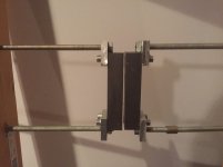
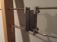
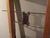
Here ar some pictures of the tiny motor. It sucks. Well not the method but the size 🙂 might be useful for stronger magnets or longer motor and even bigger membrane but for this version the frame is to big and the driven area to but hell its just an idea to build up a motor witch you can change the gap width of and use a membrane bigger then the steel bars are long and as wel keep the horizontal pieces of coil out of the gap so it moves to where it supposed to go , instead of up and down 🙂
Attachments
Interesting my friend. Its a very fast way for testing different configs. Nice job.
By the way, if you want to go with a higher magnet structure, what do you have in mind for keeping the bars straight?
Cheers
By the way, if you want to go with a higher magnet structure, what do you have in mind for keeping the bars straight?
Cheers
- Home
- Loudspeakers
- Planars & Exotics
- A DIY Ribbon Speaker of a different Kind