Yes.There is a small pinch in the curved wall as shown by the highlighted box. Although, the overall cross sectional area still increases, I guess this has to do with fact that one set of walls are flat and expanding.
If two of the horn walls were parallel, no pinch would be required. The larger the straight wall angle, the more "pinch" required to make the cross sectional area conform to the Tractrix expansion rate.
It's been my experience where tractrix horns are concerned, compression drivers with phase plugs perform better.
I think Weltersys has shown that for some applications like home hifi where ultimate high SPL is not needed - or even in some cases for pro sound reinforcement, a cone driver in a horn has less distortion that a compression driver with a phase plug. Most of this is due to fact that compression drivers have very little linear xmax and run into distortion sooner than cones with 2.5mm xmax.
Certainly Bushmeister's excellent results of low HD indicate that conventional cone drivers in a horn should be considered as an option to compression drivers.
Certainly Bushmeister's excellent results of low HD indicate that conventional cone drivers in a horn should be considered as an option to compression drivers.
And there are longstanding / used patents for ways to resolve non-linear distortions that occur inside the compression driver - The Gunness / EAW approach being real interesting: Pre-processing applies a pre-distortion to the program signal 180deg out of phase; then the compression driver's non-linearity naturally produces this same distortion out of phase and swoosh, the compression driver has much less inherent THD.
Sounds smart way anthonybisset posted reminds of feed-forward/feed-back technique used in amps.
Kees,
Thanks for the tip on the paper by EV - very useful info. I have noticed that the very small pinch that the tractrix has in the initial channel when using the tractix calculator provided by E. Forker (Volvotreter) is not always present in commercial "tractrix" designs I wonder if this pinch improves the efficiency?
Dinsdale paper (Wireless World) on horns:
http://www.volvotreter.de/downloads/Dinsdale_Horns_1.pdf
https://en.wikipedia.org/wiki/Tractrix
An externally hosted image should be here but it was not working when we last tested it.
Hi X
That paper let now that also there after 3 Khz you need correction for the fall off above that with 6 dB, so a correction filter for 3 khz and above can be 6dB cap, but I think better is a amp and a electronic filter for that, like my hybrid who get now a make over, (platefollowers get replaced with J-fet dn2540.)
Now that paper says also a faseplug will not help here, we go a new way using a K-tube for above 3 Khz.
The constant directivity of that paper, is this not better then a Tractrix?.
I do listen now a while to the horn, with the little horn in it and I do like it what concerns the resolution of the sound, but it beams more then open baffles do.
You mean the compression part in the throat as the channel? I do not now also what that will do, just testing it will help. For the making of a horn with a K-tube
is because the wideband effect is not needed of the driver I can use a bigger 8 incher or 6 incher on the troat and use that from 80 hz and up, then I get
a wideband horn with high efficienty and very low distortion, but it is not a bookshelf anymore, or you have to like very big books. But placing it on a wall
will put big to modest.
regards
kees
Last edited:
And there are longstanding / used patents for ways to resolve non-linear distortions that occur inside the compression driver - The Gunness / EAW approach being real interesting: Pre-processing applies a pre-distortion to the program signal 180deg out of phase; then the compression driver's non-linearity naturally produces this same distortion out of phase and swoosh, the compression driver has much less inherent THD.
what do we get if we predistort the mids for the reflection from the apex in a synergy?
let me try to answer my own question:
assuming half the energy injected at mid ports goes forward and half goes backwards, then we lose 3db in sensitivity but gain bandwidth, limited by the low pass filtering effect of the bandpass chamber!
assuming half the energy injected at mid ports goes forward and half goes backwards, then we lose 3db in sensitivity but gain bandwidth, limited by the low pass filtering effect of the bandpass chamber!
Harmonic distortion is frequency and amplitude dependent, applying "180deg out of phase pre-distortion" would result in additional harmonic distortion being generated.And there are longstanding / used patents for ways to resolve non-linear distortions that occur inside the compression driver - The Gunness / EAW approach being real interesting: Pre-processing applies a pre-distortion to the program signal 180deg out of phase; then the compression driver's non-linearity naturally produces this same distortion out of phase and swoosh, the compression driver has much less inherent THD.
Gunness focusing addresses four problems, distortion is not one of the correctable problems:
1) All phase plug designs produce significant smearing of the transient response.
A significant fraction of the sound energy arriving at a phase plug opening will either continue past it or reflect back from it; in either case arriving later at other phase plug slots where the sound is divided again, ad infinitum.
A carefully constructed filter falls short of perfectly correcting the axial response, but it improves it significantly, while also significantly improving the off axis response.
2) A second loudspeaker behavior, which yields well to digital preconditioning, is horn resonance.
3) A third behavior, which also yields to digital preconditioning, is cone resonance.
4) A fourth behavior is non-linear phase response of the summed crossover.
The essence of the filter to correct that defect is the high frequencies are delayed relative to the low frequencies, which counteracts the minimum phase crossover’s effect of delaying the low frequencies relative to the highs. This requires an added high frequency latency of 7 ms, the full length of the FIR filter. A nearly perfect approximation can be achieved with 1 ms or more.
All four combined can indeed make a speaker sound much better, but they do not reduce harmonic distortion.
Art
Sounds like digital preconditioning is closely related to equalization.
The phase plug problem is similar to multipath in communications, where you receive multiple copies of a signal, each with a different delay and also to high speed interconnects, where you get a reflection from every impedance discontinuity. The hardest part of any of this is training the equalizers. I'm going to look for the Gunness papers; I'm sure I'll find them interesting. The problem for me is its over 40 years since I studied the math this is based on.
The phase plug problem is similar to multipath in communications, where you receive multiple copies of a signal, each with a different delay and also to high speed interconnects, where you get a reflection from every impedance discontinuity. The hardest part of any of this is training the equalizers. I'm going to look for the Gunness papers; I'm sure I'll find them interesting. The problem for me is its over 40 years since I studied the math this is based on.
The "hardest part" has been worked out for us, though the process requires good measurement work to get really good results:The hardest part of any of this is training the equalizers. I'm going to look for the Gunness papers; I'm sure I'll find them interesting. The problem for me is its over 40 years since I studied the math this is based on.
http://www.diyaudio.com/forums/mult...hase-linearization-eq-fir-filtering-tool.html
Still on my "bucket list"...
well it seems that all the correctable distortions result in the creation of delayed echos. Many of us already have filters to correct for delayed echos in our systems but these filters are for the time scale of echos or reflections in rooms (e.g. Dirac). Gunness focussing provides separate filters for different distortion mechanisms but effectively for different time scales. The shortest time scales are associated with compression driver phase plugs, next up are those with mid-woofer cones, and finally the horn itself. Trying to do that with a single filter would result in an impossibly long (in number of taps) filter. Dividing the problem up into different filters for different time scales makes the filters practical. That isn't the way its described in the patent but I suspect the patent took the shape it did to work around patent examiner's objections - because this is really the familiar multipath problem in a different application environment and Dirac already does impulse response correction for room scale multipath.
Not to disparage the invention. Its easy for me to recognize what was done in hindsight. It was indeed creative/innovative to implement multipath correction for speaker internals in the first place.
Not to disparage the invention. Its easy for me to recognize what was done in hindsight. It was indeed creative/innovative to implement multipath correction for speaker internals in the first place.
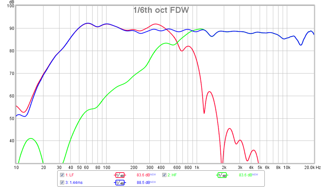
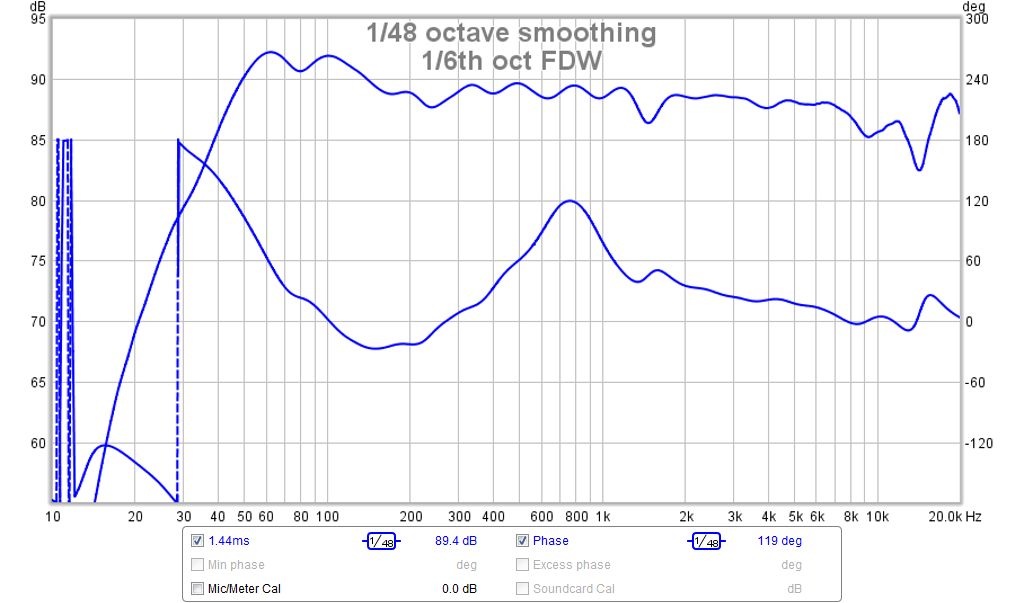
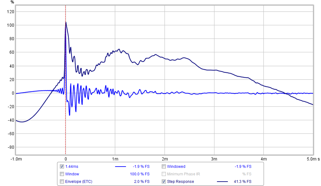
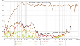
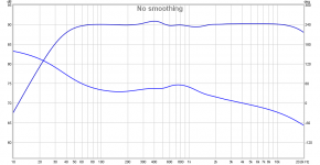
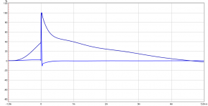
Another measurement of LTH142 and RS180P and SB65WBAC25-4
After letting the speaker rest for a couple of weeks, it seems that the glue or something may have cured some more but the measurements are a bit better now. I did switch to a TDA7498 amp with 24v power supply vs the old TPA3116 and 19v but I doubt that was the difference. The Harsch XO seems a little better now but I still can't get a flat phase with 55 deg bump. Also the step function of the woofer appears to have a negative rarefaction followed by the compression pulse which the mid/tweet rides on.
XO plot:
Phase (I settled on a 1.44ms delay of the SB65 behind the woofers):
IR/SR:
Distortion (at 0.5m and -6dB below 2.83v):
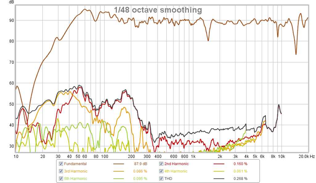
I am listening to it again and sounds very good on drums, stand up bass, guitar, and piano.
After letting the speaker rest for a couple of weeks, it seems that the glue or something may have cured some more but the measurements are a bit better now. I did switch to a TDA7498 amp with 24v power supply vs the old TPA3116 and 19v but I doubt that was the difference. The Harsch XO seems a little better now but I still can't get a flat phase with 55 deg bump. Also the step function of the woofer appears to have a negative rarefaction followed by the compression pulse which the mid/tweet rides on.
XO plot:
Phase (I settled on a 1.44ms delay of the SB65 behind the woofers):
IR/SR:
Distortion (at 0.5m and -6dB below 2.83v):
I am listening to it again and sounds very good on drums, stand up bass, guitar, and piano.
Attachments


Last edited:
Xrk971,The Harsch XO seems a little better now but I still can't get a flat phase with 55 deg bump. Also the step function of the woofer appears to have a negative rarefaction followed by the compression pulse which the mid/tweet rides on.
Phase (I settled on a 1.44ms delay of the SB65 behind the woofers):
It looks like the delay and filters you are using is putting the HF almost one wavelength behind the bandpass woofer, resulting in the "up and down" phase changes through the crossover region.
The offset horn bandpass introduces a phase lag compared to the "normal" horn phase response of the HF (which is also different than the phase response of the front loaded drivers that the Harsch crossover is designed for).
The HF location physically behind the bandpass mids should result in a near flat phase response through the crossover region using symmetrical filters and no (or very little) delay on either the HF or LF.
It is possible to achieve flat (or smooth) phase through the crossover region in this type of design with passive components and no delay. In your horn since the woofer ports are a bit closer to the mouth compared to the usual location closer to the throat, the woofer may need a fraction of a ms to phase align through the crossover region.
Art
xrk971,
Some comparison plots in same X Y scales as yours, system stopbands set as BW2 at 37Hz/22kHz, HARSCH XO point 500Hz tweeter delayed 1mS.
SR starting over 40% negative looks like you have got a FIR filter turned on : ) have you any strange setting in miniDSP that belong to another setup that by accident is turned on.
Low pass slope for woofers is not special smooth it looks like three notches (360Hz/800Hz/1,4kHz) probably from symmetric band pass port, have you any PEQ's left to smooth them a bit.
Attachments

Xrk971,
It looks like the delay and filters you are using is putting the HF almost one wavelength behind the bandpass woofer, resulting in the "up and down" phase changes through the crossover region.
The offset horn bandpass introduces a phase lag compared to the "normal" horn phase response of the HF (which is also different than the phase response of the front loaded drivers that the Harsch crossover is designed for).
The HF location physically behind the bandpass mids should result in a near flat phase response through the crossover region using symmetrical filters and no (or very little) delay on either the HF or LF.
It is possible to achieve flat (or smooth) phase through the crossover region in this type of design with passive components and no delay. In your horn since the woofer ports are a bit closer to the mouth compared to the usual location closer to the throat, the woofer may need a fraction of a ms to phase align through the crossover region.
Art
Agreed with all of this above. I tend to pack my mids a lot closer than Danely does, and since I generally use direct radiators instead of compression drivers, I don't have the delay that's introduced in the throat of the compression driver itself. The steps mentioned by Art work for me.
Another one, that's a bit annoying, is that some manufacturers mislabel the positive and negative. So take a look at the impulse response of each driver and verify that what's labeled "positive" actually produces a positive spike in the measured impulse response.
There is something strange going on with my bandpass setup. The first pulse is followed by a larger negative pulse - so my thinking was to get the most impact I would align the tweeter with the second pulse by flipping the polarity of the woofer and delaying it an additional time period. This is why the leading edge has got a negative offset. This is the residual first pulse of the woofer which is the opposite sense. I tried time aligning with the first and it sounds better with the second. I don't have any wierd settings in miniDSP causing this. It is present when running full range with just an amp and removing miniDSP. It may be the extra long duct from the driver to the horn and maybe having the small holes act as an impedance mass loading of the duct. I did not model this detail of system so I don't have the multiple pulse in the sims. Cutting a bigger hole in the horn wall may fix this.
Adding delay that would not be required if the polarity were not reversed.. The first pulse is followed by a larger negative pulse - so my thinking was to get the most impact I would align the tweeter with the second pulse by flipping the polarity of the woofer and delaying it an additional time period.
- Home
- Loudspeakers
- Multi-Way
- A Bookshelf Multi-Way Point-Source Horn