Not a measurement request but you might be able to answer this one. In the eighteen sound drawing it looks as if the waveguide narrows down from the throat entry before widening out again. Is this what you see or is this a weird drawing. I have looked at pictures and it is hard to decide.

BTW last measurements look really good 🙂
BTW last measurements look really good 🙂
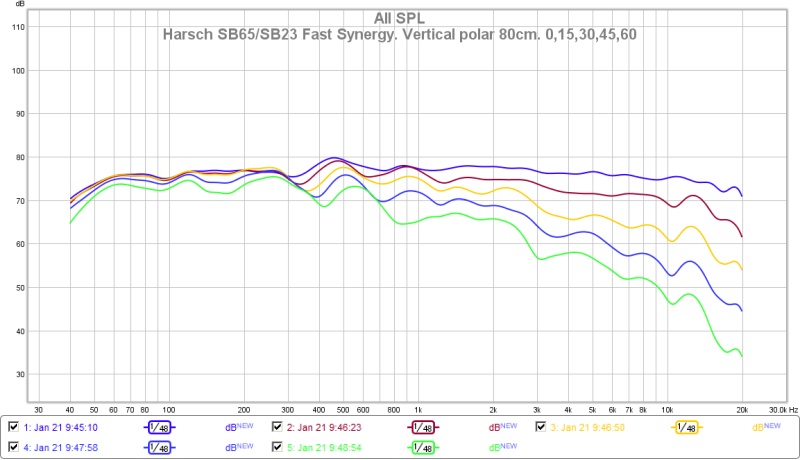
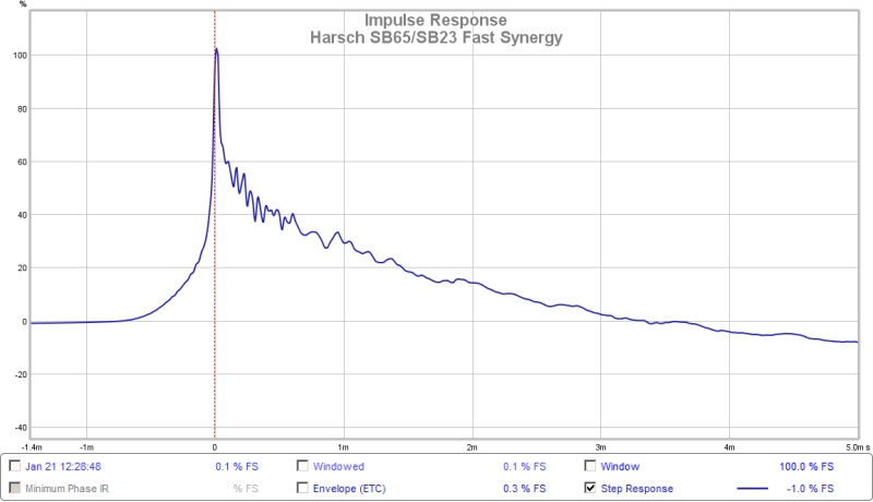
Just some view of the measurement already made. I'd like to see from that last plot, a waterfall view with settings close to this:

Just to see how that first wave front looks to about ~300 Hz. But You don't need more measurements for that. It will be fun to compare this to the final version with the extra woofer mounted.
Just to see how that first wave front looks to about ~300 Hz. But You don't need more measurements for that. It will be fun to compare this to the final version with the extra woofer mounted.
Here is another try - Harsch xover lower to 500hz and delay reduced a little.....
What do you reckon wesayso?
Did you use digital crossover and delay? and just a wideband or with a extra tweeter?, thanks.
regards
Done!
So - I am gonna start listening to stuff now!
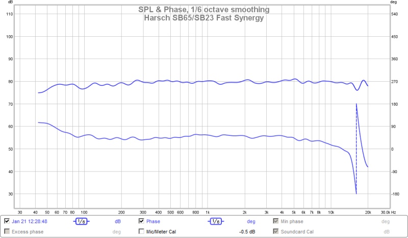
That phase is amazingly flat - where is the 55deg Harsch bump at 500Hz XO? Maybe 1/6th oct smoothing got rid of it?
Beautiful! Now you are cooking with gas! 😀
Great job Bushmeister!

Last edited:
The Santa Claus Machine works!
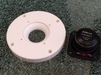
3 hours and 51 minutes of printing and here is the object d'art I awoke to.
There really is a Santa Claus 🙂
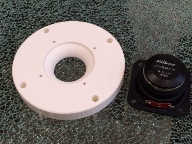

I just need to find some long M6 bolts and nuts, and some thin open cell foam to stick in the chamber around the surround.
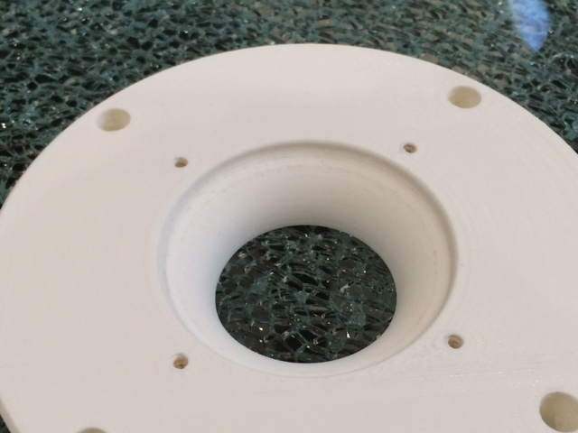
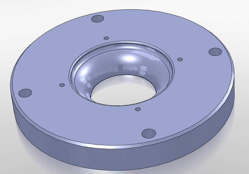
I am a little worried that I made the adapter too deep - but I wanted a nice smooth transition from 2.1in dia to 1.41in dia using a 0.50in radius roundover. We will see if it is too much of a bandpass chamber that will ruin my HF extension.
This throat adapter is 0.625in thick and has a 0.50in radius round throat. 0125in deep space provided for surround and damping foam clearance.
Overall dia is 4.72in.
3 hours and 51 minutes of printing and here is the object d'art I awoke to.
There really is a Santa Claus 🙂
I just need to find some long M6 bolts and nuts, and some thin open cell foam to stick in the chamber around the surround.
I am a little worried that I made the adapter too deep - but I wanted a nice smooth transition from 2.1in dia to 1.41in dia using a 0.50in radius roundover. We will see if it is too much of a bandpass chamber that will ruin my HF extension.
Attachments

Last edited:
Just some view of the measurement already made. I'd like to see from that last plot, a waterfall view with settings close to this:
Just to see how that first wave front looks to about ~300 Hz. But You don't need more measurements for that. It will be fun to compare this to the final version with the extra woofer mounted.
Hope this is right:
Attachments

Yes this is the view I wanted to see. For your own reference you might want to limit the graph to about 30 dB down from the average value. That nice and clear ridge of sound is what I wanted to see. I'm expecting a second woofer to make a difference on the low end. The top pretty much stays as is. The bigger that instant drop gets, the clearer the sound. That's what makes line arrays good performers between 100 Hz and 5000 Hz.
Last edited:
Yes the throat narrows, you can also clearly see that in post #267.Not a measurement request but you might be able to answer this one. In the eighteen sound drawing it looks as if the waveguide narrows down from the throat entry before widening out again. Is this what you see or is this a weird drawing. I have looked at pictures and it is hard to decide.
View attachment 526456
BTW last measurements look really good 🙂
Narrowing is required to get wide dispersion, the "pinched" width being approximately the wavelength of the highest frequency where dispersion equals the nominal pattern of the horn. Lateral reflections off the horn walls can increase HF dispersion, but the response is chaotic, varying in pattern with frequency depending on the phase deviations resulting from differing path length of the reflections.
Without the narrow throat, the HF dispersion is dictated largely by the native dispersion of the cone used. Of note, the cross sectional area must continue to expand through the pinched area or a band pass chamber will form, reducing HF level, and adding delayed reflected HF energy, "smearing" the HF impulse response.
Art
Last edited:
LOL! You're probably right mayhem!
I just can't help myself! As you say - it is more just a proof of concept as it seems like such a nice point source design with excellent controlled directivity, I just want to see if I can get a nice step and phase too!
Enclosures will take weeks/months to build as it is so cold and wet here and I will need to do it outside. Plus my missus isn't too keen on the 'alien wrapped in blankets' in the study, so I am making the most of this opportunity!
Even a cardboard box with taped seams would be more beneficial to get a window into how the woofers will behave. After all the hard work you've already put in, i'd get the woofers loaded and take a look. Ive done lots of cardoid work and testing and find the response in the pass band is smoothed substantially by the inverse phase signal.......and that's a great thing IMO as long as there's no significant sacrifice to extension or efficiency. My take on the synergy approach has always been about power handling and efficiency. In a small enclosure approach, fundamentally the goals for me would need to be sustained......if not, a waveguide two way makes more sense. I can build a waveguide two way with 10" woofers active cardoid in a box not much different in size than a bookshelf synergy which would hold pattern control to 400hz or lower. Proof of concept is certainly valuable and youve done some great work...........but it all comes down to the question of could vs should.
Even a cardboard box with taped seams would be more beneficial to get a window into how the woofers will behave. After all the hard work you've already put in, i'd get the woofers loaded and take a look. Ive done lots of cardoid work and testing and find the response in the pass band is smoothed substantially by the inverse phase signal.......and that's a great thing IMO as long as there's no significant sacrifice to extension or efficiency. My take on the synergy approach has always been about power handling and efficiency. In a small enclosure approach, fundamentally the goals for me would need to be sustained......if not, a waveguide two way makes more sense. I can build a waveguide two way with 10" woofers active cardoid in a box not much different in size than a bookshelf synergy which would hold pattern control to 400hz or lower. Proof of concept is certainly valuable and youve done some great work...........but it all comes down to the question of could vs should.
For me it's the Synergy's ability to hold the pattern up and down and left to right. Being coincidental by nature in their output with minimum path length differences is key here. A more traditional 2 way with a horn and woofer won't ever do as well when you move around that ideal spot. The distance between the woofer and tweeter is gone (well most of it) in the synergy concept. Even when viewed from the listeners perspective. Look at distance from ear to each source for the synergy and the more conventional wave guide/woofer setup and start to move in each direction. Observe the true difference in those distances. Very few speakers I can come up with do that. It has my preference though.
Last edited:
First measurement of FR58EX in LTH142
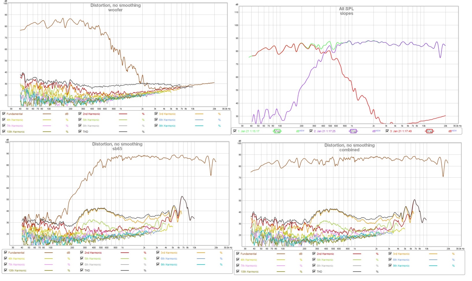
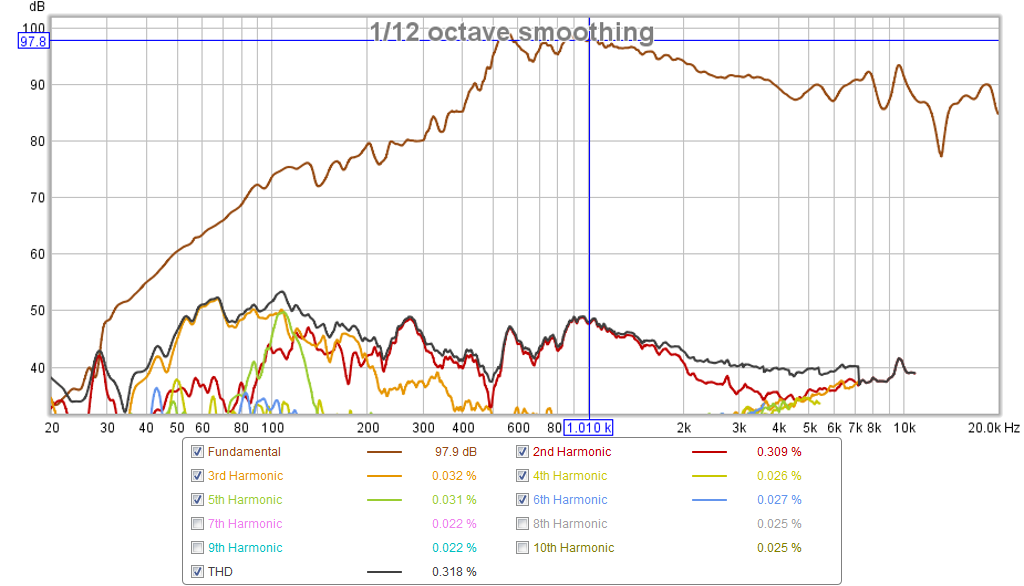
Here is a quick measurement with no damping foam in the driver chamber. Mic is 0.5m away and -6dB below 2.83v drive voltage (so it should give equivalent sensitivity at 2.83v and 1m, but distortion will be less). A heavy blanket is wrapped around the back of the driver (no rear chamber).
It looks like the smooth roundover is working and the chamber depth is not causing a bandpass dropoff. The gain of the horn appears to kick in at 500Hz and there is about a 10dB falloff towards HF. There are some peaks and dips that hopefully, with the damping foam, will smooth out.
Not a bad first try I think.
Attachments
X, what does it look like with a 1/6 octave window? The distortion plot is mighty clean!
Is the transition from 3D print to horn seamless?
Is the transition from 3D print to horn seamless?
X, what does it look like with a 1/6 octave window? The distortion plot is mighty clean!
Is the transition from 3D print to horn seamless?
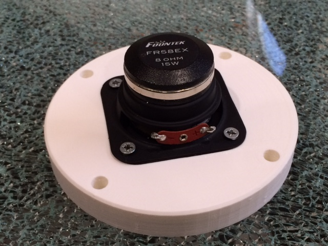
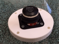
The part was essentially ready to use, I just had to peel off the temporary support structures underneath where the hollowed out areas are. I took some 150 grit sandpaper to the roundover for a little smoothing. Probably could have done without it. The biggest problem was an operator error. I use a base circle dia for the bolts of 4.150 in dia when it was supposed to be 4.015in dia. So the M6 bolts did not line up. I just switched to smaller #6 bolts to make it work temporarily. The throat dia matched perfectly to the WG and I used a 2mm thick sheet of EVA foam gasket between the WG and the adapter.
It was pretty good in general - and my printer behaved this time unattended print for 4hrs.
Here is 1/6th octave window (under IR Window dialog, frequency dependent window option):
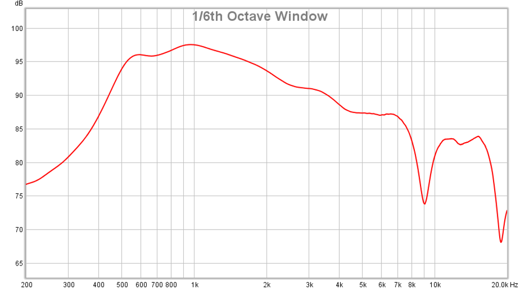
Looks like I need to work on the cancellation dip at 9kHz - corresponds to a half-wave distance of 1.5in.
Attachments

Last edited:
Here is a quick measurement with no damping foam in the driver chamber. Mic is 0.5m away and -6dB below 2.83v drive voltage (so it should give equivalent sensitivity at 2.83v and 1m, but distortion will be less). A heavy blanket is wrapped around the back of the driver (no rear chamber).
It looks like the smooth roundover is working and the chamber depth is not causing a bandpass dropoff. The gain of the horn appears to kick in at 500Hz and there is about a 10dB falloff towards HF. There are some peaks and dips that hopefully, with the damping foam, will smooth out.
Not a bad first try I think.
Xrk971,
Having seen damping foam degrade and disintegrate (especially when subjected to high SPL) over time my preference would be felt damping, or no damping for maximum output.
As an A/B comparison it would be interesting to see the difference in response with the driver mounted directly on the 1.4" flange using an appropriate standoff spacer (easily cut from a cereal box with an Xacto knife, or printed with your fancy machine).
If your horn responds similarly to the throat changes as I have found with my experiments, it may increase output in the lower octaves, have one steep notch around 6kHz, and smooth the response above.
Does the horn you are using have any undercut (throat pinch) or is 1.4" the minimum dimension?
Art
Last edited:
As an A/B comparison it would be interesting to see the difference in response with the driver mounted directly on the 1.4" flange using an appropriate standoff spacer (easily cut from a cereal box with an Xacto knife, or printed with your fancy machine).
If your horn responds similarly to the throat changes as I have found with my experiments, it may increase output in the lower octaves, have one steep notch around 6kHz, and smooth the response above.
Does the horn you are using have any undercut (throat pinch) or is 1.4" the minimum dimension?
A plain standoff would have the sharp 90deg lip and potential for leaks as the flange is a steel plate bolted onto the WG round section. I guess some sealing compound at the gap could work. I could use a disc of foam core and was temped to.
I could try some felt in there but curious if the foam style surround Bushmeister used worked so effectively to smooth out those peaks.
The horn throat is narrowest at 1.41 in dia. It immediately expands at a 7.5 deg angle after the throat.
The part was essentially ready to use, I just had to peel off the temporary support structures underneath where the hollowed out areas are. I took some 150 grit sandpaper to the roundover for a little smoothing. Probably could have done without it. The biggest problem was an operator error. I use a base circle dia for the bolts of 4.150 in dia when it was supposed to be 4.015in dia. So the M6 bolts did not line up. I just switched to smaller #6 bolts to make it work temporarily. The throat dia matched perfectly to the WG and I used a 2mm thick sheet of EVA foam gasket between the WG and the adapter.
It was pretty good in general - and my printer behaved this time unattended print for 4hrs.
Here is 1/6th octave window (under IR Window dialog, frequency dependent window option):
Looks like I need to work on the cancellation dip at 9kHz - corresponds to a half-wave distance of 1.5in.
It will be interesting to see if we can find a fool proof recipe to eliminate such a dip. Bushmeister's practice seems to work quite well and we don't need the
absolute SPL Art is looking for in our homes. Though in getting to the bottom of it the test data Art proposes is good to have. A foam core seal might work instead of the cereal box gasket. Do you have some of that stuff Jeshi used for enclosures?
So I'm looking for a JMLC with a 1.4" throat... (just kidding!)
The part was essentially ready to use, I just had to peel off the temporary support structures underneath where the hollowed out areas are. I took some 150 grit sandpaper to the roundover for a little smoothing. Probably could have done without it. The biggest problem was an operator error. I use a base circle dia for the bolts of 4.150 in dia when it was supposed to be 4.015in dia. So the M6 bolts did not line up. I just switched to smaller #6 bolts to make it work temporarily. The throat dia matched perfectly to the WG and I used a 2mm thick sheet of EVA foam gasket between the WG and the adapter.
It was pretty good in general - and my printer behaved this time unattended print for 4hrs.
Here is 1/6th octave window (under IR Window dialog, frequency dependent window option):
Looks like I need to work on the cancellation dip at 9kHz - corresponds to a half-wave distance of 1.5in.
did you seal the surfaces of the adapter?.......3d is pourous so there could be some rear wave interference through the adapter
- Home
- Loudspeakers
- Multi-Way
- A Bookshelf Multi-Way Point-Source Horn