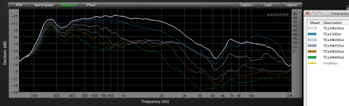
The charts on the left are the TC9 with (approximately) .3 liter compression chamber on the Maltese horn, "TC+2Monin" is the 2.5" throat entrance Maltese horn on axis tested inside at 24", "TCMonin" is the 2" throat entrance Maltese horn on axis tested inside at 24".Weltersys,
Those horns really did get cut down to achieve the matching throat! Ouch! Can you explain the differences in the plots? What are we looking at? Are the smoother lower graphs the cut down ones with a rounded throat?
Also, I don't know what you mean by this:
"It is interesting that the TC9 loaded Maltese horn actually has smoother response than the driver as a front loaded unit."
Isn't the TC9 a front loaded driver in the Maltese?
Thanks for the photos of closeups of the throat region and the rear chamber box.
Phase response is above magnitude response.
The upper charts are unsmoothed, lower are a repeat, smoothed.
The left hand charts are the polars of the TC9 with a 1 liter rear chamber (bottle) the same diameter as the driver, "no baffle" (front loaded), the upper charts are unsmoothed, lower are smoothed.
As you can see, the "no baffle" TC9 has more jagged response (though just a smooth upward rising response on axis), +/-4 dB of "ripple", while driving the Maltese horns, "ripple" is only about +/- 1 dB .
Art
Ok, I get it. A baffle less or in this case a round baffle the same diam as driver has about the worst baffle diffraction you can get so not surprising it is less inside the Maltese as a FLH. 1dB ripple is excellent though anyway you look at it.
I am not familiar with the Maltese horn - it looks pretty skinny - what type of expansion is it? I guess mounted in a 4x4 cell you get your desired dispersion (45deg?).
I am not familiar with the Maltese horn - it looks pretty skinny - what type of expansion is it? I guess mounted in a 4x4 cell you get your desired dispersion (45deg?).
The Maltese is a conical expansion horn, originally designed in 1991 as the high frequency portion of a 3 way system, nested inside a mid horn nested inside a bass horn. The dispersion is a bit wider than the 13 degree horn angle, so a pair do around 50 degrees, though some "waistbanding" from 700 Hz to 2500 Hz. The chart below shows the polars of a pair side by side, inner horn walls parallel. With some minor changes to the mouths to get the inner horn walls a bit closer together (from about 3" to 1.5", a pole mount will go between the horns) I expect some minor polar response improvement.I am not familiar with the Maltese horn - it looks pretty skinny - what type of expansion is it? I guess mounted in a 4x4 cell you get your desired dispersion (45deg?).
The original (larger) cardboard prototype used a 2" Radio Shack 100 milliwatt "Mini Amp" taped on, my experiments with "full range" drivers on horns go back 25 years!
Art
Attachments
Last edited:
Weltersys,
Cool concept of Russian Dolls for nested horns. I did not realize you have played with full range drivers in horns for that long. Glad the TC9 is working out for you. Who would have figured a $10 paper cone can serve pro sound reinforcement duties. 🙂
Regarding your taped on 100mW RS amp, technology has come a long way. I recently tested a very small TPA3118D2 amp the size of a large postage stamp that is a bonafide 60watts. Probably more than enough to drive a TC9 in a Maltese. You can tape it on the back of the rear chamber even.
More info here http://www.diyaudio.com/forums/class-d/219730-tpa3118d2-25.html#post4585203
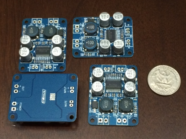
I ran stress test at true 60w and it never tripped thermal shutdown despite using the PCB as the heatsink. These amps are exceptional clean sounding with great transparency and bass authority. About $7 to $9 ea.
Cool concept of Russian Dolls for nested horns. I did not realize you have played with full range drivers in horns for that long. Glad the TC9 is working out for you. Who would have figured a $10 paper cone can serve pro sound reinforcement duties. 🙂
Regarding your taped on 100mW RS amp, technology has come a long way. I recently tested a very small TPA3118D2 amp the size of a large postage stamp that is a bonafide 60watts. Probably more than enough to drive a TC9 in a Maltese. You can tape it on the back of the rear chamber even.
More info here http://www.diyaudio.com/forums/class-d/219730-tpa3118d2-25.html#post4585203
I ran stress test at true 60w and it never tripped thermal shutdown despite using the PCB as the heatsink. These amps are exceptional clean sounding with great transparency and bass authority. About $7 to $9 ea.
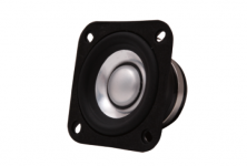
DC200-8 woofers and FR58EX mid/tweeter
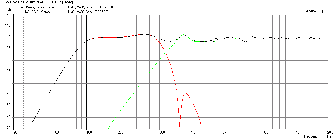
While waiting for my Faital Pro WG and DC200-8 woofers to arrive, I decided to model the system with the Fountek FR58EX driver. This driver has some really nice TS parameters for horn loading. A stronger lower Qts motor than the SB56WBAC25-4, and 2.9mm of xmax (although we will see that only 0.5mm of displacement is needed to match up with the DC200-8), leaving a lot of headroom to EQ the circa 12dB high shelf to flatten the top power response. I had to move the XO point to 570Hz to get a better integration. It will depend on how the WG loads the driver. As I will be using the Faital Pro LTH142 which is a tractrix, so it may achieve lower frequency horn loading.
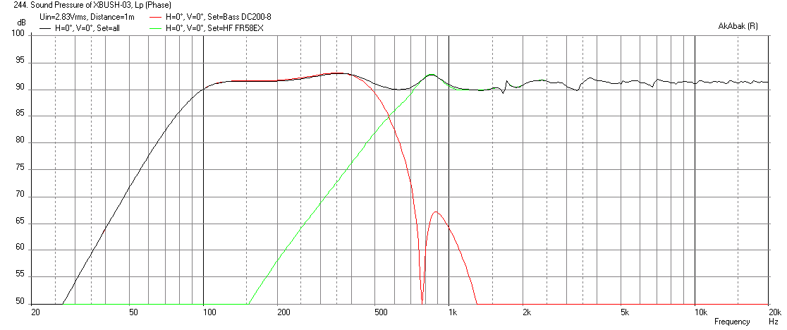
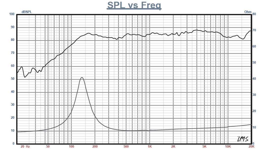
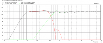
The DC200-8's are not as sensitive as the SB23's but the price is right 🙂. I am able to achieve about a 91.6dB sensitivity at 2.83v at 1m for the system with an f2 of 91Hz. Maximum SPL is 110dB if excursion limited - and this is a little bit over the max rms thermal limit but not max crest limit.
Here is the predicted SPL at xmax for the woofers:
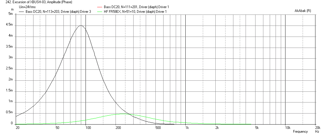
Here is the corresponding cone excursion, note that the FR58EX is only going to 0.5mm which will really keep the HD low as xmax is nearly 3mm:
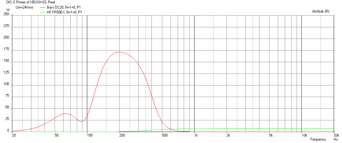
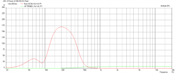
Here is the corresponding electrical input at max SPL, note only 7w is being used for FR58EX, leaving headroom for boost EQ to flatten HF response:
Here is the sensitivity at 2.83v and 1m, about 91.6dB:
Clearly, the performance is not as high as the SB23 and SB65 combo, but the woofers are about $50 a pair vs $180/pair for the SB23's.
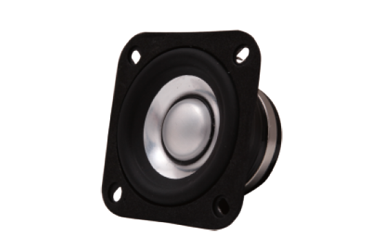
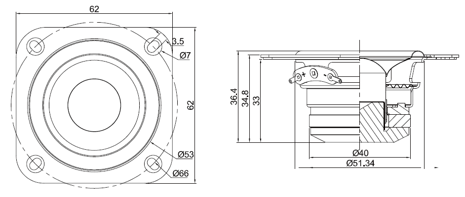
The shape of the FR58EX bezel is already designed for backside mounting as it has a foam gasket on the bezel face, and the bezel is very low profile. I think a very low volume adapter plate with nice radiused edges can be made to transition the FR58EX surround to the WG throat.
While waiting for my Faital Pro WG and DC200-8 woofers to arrive, I decided to model the system with the Fountek FR58EX driver. This driver has some really nice TS parameters for horn loading. A stronger lower Qts motor than the SB56WBAC25-4, and 2.9mm of xmax (although we will see that only 0.5mm of displacement is needed to match up with the DC200-8), leaving a lot of headroom to EQ the circa 12dB high shelf to flatten the top power response. I had to move the XO point to 570Hz to get a better integration. It will depend on how the WG loads the driver. As I will be using the Faital Pro LTH142 which is a tractrix, so it may achieve lower frequency horn loading.
The DC200-8's are not as sensitive as the SB23's but the price is right 🙂. I am able to achieve about a 91.6dB sensitivity at 2.83v at 1m for the system with an f2 of 91Hz. Maximum SPL is 110dB if excursion limited - and this is a little bit over the max rms thermal limit but not max crest limit.
Here is the predicted SPL at xmax for the woofers:
Here is the corresponding cone excursion, note that the FR58EX is only going to 0.5mm which will really keep the HD low as xmax is nearly 3mm:
Here is the corresponding electrical input at max SPL, note only 7w is being used for FR58EX, leaving headroom for boost EQ to flatten HF response:
Here is the sensitivity at 2.83v and 1m, about 91.6dB:
Clearly, the performance is not as high as the SB23 and SB65 combo, but the woofers are about $50 a pair vs $180/pair for the SB23's.
The shape of the FR58EX bezel is already designed for backside mounting as it has a foam gasket on the bezel face, and the bezel is very low profile. I think a very low volume adapter plate with nice radiused edges can be made to transition the FR58EX surround to the WG throat.
Attachments
-
 xbush-03-dc200-8-fr58ex-max-spl.png35.1 KB · Views: 705
 -
 xbush-03-dc200-8-fr58ex-max-displ-24v.png13 KB · Views: 695
 -
 xbush-03-dc200-8-fr58ex-electrical-power-24v.png10.6 KB · Views: 698
 -
 xbush-03-dc200-8-fr58ex-SPL-2.83v.png13.7 KB · Views: 681
 -
 fr58ex-spl.png44.8 KB · Views: 666
 -
 fr58ex-interface-dwg.png46.3 KB · Views: 897
 -
 fr58ex-photo.png86.7 KB · Views: 681
Last edited:
I like the Fountek58 idea!
I'll have to try this with my TBs (they max out at 0.5mm xmax) and they may just cope 🙂
I'll have to try this with my TBs (they max out at 0.5mm xmax) and they may just cope 🙂
Mondogenerator:
Tang Band w2-852SH's work well for this application. They have even a more powerful motor, much higher sensitivity, but less xmax. So you may not need them to move much to keep up.
What WG are you thinking of using?
Tang Band w2-852SH's work well for this application. They have even a more powerful motor, much higher sensitivity, but less xmax. So you may not need them to move much to keep up.
What WG are you thinking of using?
Mondogenerator,I like the Fountek58 idea!
I'll have to try this with my TBs (they max out at 0.5mm xmax) and they may just cope 🙂
Problem is .5mm Xmax results in -13dB less clean output compared to the 2.5mm Xmax drivers being discussed.
I have one hundred .5mm Xmax cones for sale in line array cabinets if anyone is interested...
Art
Weltersys,
You have a good point. One of the big attractions with full range cone drivers in horns is that the horn loading keeps displacement at a fraction of the full xmax, so the cone is barely moving. This is partly why the HD figures are so low, and the difference is audible to my ears. -50dB to -55dB HD levels are excellent if you can get it.
What were the HD levels you were getting in your Maltese with the TC9FD? Say reference to 95dB or 105dB at 1m?
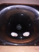
Progress is being made. These are some of the very messy mid production shots.....😛
Attachments

Last edited:
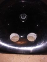
As you can see there is a very deep layer of structural epoxy building up the horn to a flat mounting surface. A disc of MDF is then glued to this and then using a hole saw two 6cm diameter ports have been cut.
I need to route out the holes to provide better flow, but couldn't help taking some measurements as it is, just to see how it affected the power response - I was really worried it would screw it up.....
I need to route out the holes to provide better flow, but couldn't help taking some measurements as it is, just to see how it affected the power response - I was really worried it would screw it up.....
Attachments

Yay! You're well on your way! Very good results so far! I can imagine the suspense you felt getting that measurement done.
What do you mean by "route out the holes"? I was going to suggest "frustrum"ize some way as discussed in the patent. At the very least go around the holes with a V-bit to widen them out on the side towards the driver Is that what you are thinking?
Yay! You're well on your way! Very good results so far! I can imagine the suspense you felt getting that measurement done.
Yep - I was dreading it all turning to the brown stuff!!
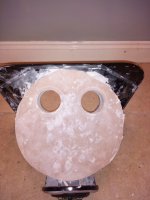
nc535 - that is exactly what I am doing! each hole from the MDF side will look like a funnel down to the circular tap into the horn.
I have just used a 5cm wide v-bit, then I will use a file to gently taper them down in a smooth curve.
Then I have to do the same work on the other side of the horn (two woofers per horn). Then sand and polish around the taps to make everything shine. Then paint the MDF and epoxy a nice mat black. Then mount the woofers.....
Then the fun begins! 😀
However, I wasn't going to embark on all that without checking to make sure cutting those holes out didn't totally screw up the horns freq response.
Hence the measurements whilst they look so rough and ready!
Great progress! So was there a substantial difference with/without the holes? Looks like not.
I think this data looks solid:
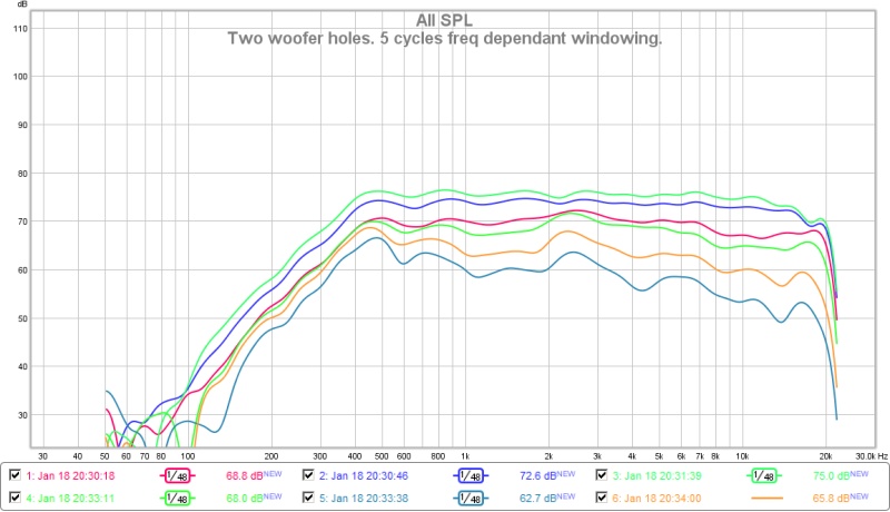

You are very close now.
Regarding frustrums - that will increase the front chamber volume - which may decrease the upper bandwidth notch location. I would first put a round over on those 5cm holes and mount the drivers and measure the bass response. The model with a 30mm duct from woofer to horn wall seems to work fine. So not sure if all that manual labor of making a big funnel is worth it - especially if it messes up the response. You can always widen the funnel later if it does not work with a simple hole and and roundover.
I think this data looks solid:
You are very close now.
Regarding frustrums - that will increase the front chamber volume - which may decrease the upper bandwidth notch location. I would first put a round over on those 5cm holes and mount the drivers and measure the bass response. The model with a 30mm duct from woofer to horn wall seems to work fine. So not sure if all that manual labor of making a big funnel is worth it - especially if it messes up the response. You can always widen the funnel later if it does not work with a simple hole and and roundover.
Last edited:
Nested horns
See also here - I thought this was pretty cool
http://www.diyaudio.com/forums/multi-way/243880-nested-horns.html
Weltersys,
Cool concept of Russian Dolls for nested horns...
See also here - I thought this was pretty cool
http://www.diyaudio.com/forums/multi-way/243880-nested-horns.html
Don't forget to leave the room for the surrounds to move! 😉
Looking very promising so far. Take your time to do it right. I'd say it's worth the attention you pay to it. This looks very promising indeed!
Looking very promising so far. Take your time to do it right. I'd say it's worth the attention you pay to it. This looks very promising indeed!
Don't forget to leave the room for the surrounds to move! 😉
Looking very promising so far. Take your time to do it right. I'd say it's worth the attention you pay to it. This looks very promising indeed!
Don't worry - I will be using ply/DMF rings to stand off the drivers to allow no contact even at full x-max!
I agree with taking my time.
Actually I think the freq response has possibly improved with the woofer taps added - I can only guess this is to do with the act of removing the SB65, and remounting it. Or perhaps the addition of 1kg of structural epoxy....
Anyway these things are going to end up being really solid. Each horn will need 2-3kg of epoxy. Then the MDF mounting plate, then the surround ring, then the woofers....
I don't think I will need to worry too much about damping.
As soon as I have both woofers mounted I will start taking some measurements and report back....😀
Regarding frustrums - that will increase the front chamber volume - which may decrease the upper bandwidth notch location. I would first put a round over on those 5cm holes and mount the drivers and measure the bass response. The model with a 30mm duct from woofer to horn wall seems to work fine. So not sure if all that manual labor of making a big funnel is worth it - especially if it messes up the response. You can always widen the funnel later if it does not work with a simple hole and and roundover.
Good advice X, plus that will save me some elbow grease!
I will keep the frustrum to a reasonable size....
Don't worry - I will be using ply/DMF rings to stand off the drivers to allow no contact even at full x-max!
I agree with taking my time.
Actually I think the freq response has possibly improved with the woofer taps added - I can only guess this is to do with the act of removing the SB65, and remounting it. Or perhaps the addition of 1kg of structural epoxy....
Anyway these things are going to end up being really solid. Each horn will need 2-3kg of epoxy. Then the MDF mounting plate, then the surround ring, then the woofers....
I don't think I will need to worry too much about damping.
As soon as I have both woofers mounted I will start taking some measurements and report back....😀
Makes sense, though I sort of expected a routered groove in the current MDF piece for the surround to fit into, to keep/get the chamber volume under the cone as small as possible. Is this MDF piece the part that sits in the cone perhaps?
As is I couldn't understand the fixation of that MDF piece to the horn before routing that groove 🙂. Looking forward to following this journey.
Last edited:
- Home
- Loudspeakers
- Multi-Way
- A Bookshelf Multi-Way Point-Source Horn