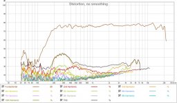
Have you guys worked out a solution for the suckouts at 6k and 14k?
I think much different builds, much different outcomes, smooting things will help, or use strong motor drivers with stiff cone, yes I now the visaton is also not perfect the rubber surround is not as good as textile.
Have you guys worked out a solution for the suckouts at 6k and 14k?
When I hear term "suckout" I think of a room reflection causing a broader dip, typically there is one at 150Hz with almost all speakers at typical listening height due to floor bounce cancellation.
The narrow cancellation dips here at 5.8kHz and ~14kHz are caused by a reflection cancellation at the driver and throat. They are actually quite narrow and not that audible is my guess. We may try mildly EQ a bit to fill it in, or some more work can go into smoothing things around the throat some more - but my guess is that this will only go away with a phase plug. We need to be careful not to put any compression ratio on the phase plug as this driver does not have the motor to keep up with it.
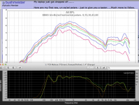
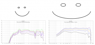
xrk971,It's because what Wesayso is suggesting is to EQ at listening position which has a mix of reflections and direct sound. I measured at 0.5m and with 5ms hating can get rid of all first reflections. But I guess at LP or would look different and what we want here is a broad stroke of a how to help the response of not just the direct sound. At least that is how I am interpreting this.
Your measurements at .5 meter (and gating) effectively remove much of the room contribution, but may not accurately reflect the polar response of your horn, which IIRC, is larger than .5 meters across the longest dimension.
To accurately obtain phase information at different angles requires rotating the cabinet around the acoustic center, which can change in frequency depending on horn design and the HF driver used.
In regard to full range frequency measurements, Pat Brown (who is an expert in the field, does DSLs Sy measurements, amongst many others) wrote :
"A working “rule-of-thumb” for determining the boundary between near-field and far-field is to make the minimum measurement distance the longest dimension of the loudspeaker multiplied by 3.
He then writes:
It is often thought that a remote measurement position is necessary for low frequencies since their wavelengths are long. Actually the opposite is true. It is more difficult to get into the far-field of a device at high frequencies, since the shorter wavelengths make the criteria in Item 4 more difficult to satisfy.
Item 4:
4. The distance from the source where the path length difference for wave arrivals from points on the device on the surface plane perpendicular to the point of observation are within one-quarter wavelength at the highest frequency of interest (Figure 2).
This is an important distinction between high frequency and low frequency measurement, criteria #4 can be satisfied at 95 Hz for a subwoofer of one square meter measured at one meter, but to satisfy the same criterion for a one meter mid/high horn to 16 kHz would require a very long distance."
Wesayso and others with line arrays literally can't get into the far feild of their speakers in usual domestic listening environments, but the further from the source, the less the near field interference problems confuse the "wizard".
As far as the "Room EQ Wizard", a wizard that suggests the same "Q" for varying "Q" problems sounds like a one trick wizard to me 😉.
Art
We need to be careful not to put any compression ratio on the phase plug as this driver does not have the motor to keep up with it.
That is what I think also, a compression driver cone is very stiff metal and have big magnet.
But we try I see what happens.
That is what I think also, a compression driver cone is very stiff metal and have big magnet.
But we try I see what happens.
We can buy magnets will it help Scan-Speak Magnets > Loudspeaker Freaks.
Attachments

Your measurements at .5 meter (and gating) effectively remove much of the room contribution, but may not accurately reflect the polar response of your horn, which IIRC, is larger than .5 meters across the longest dimension.
This is the uTrynergy with an 8.5in x 13in mouth, 13in is about 0.33m.
To accurately obtain phase information at different angles requires rotating the cabinet around the acoustic center, which can change in frequency depending on horn design and the HF driver used.
That will take some work and you are saying it should be rotated at where the voice coil is? That would cause a huge theta x R effect of swinging the horn face around and you have this big lateral offset of the horn mouth with angle. I rotate about an axis on the horn face.
I calculated the max SPL at 500Hz for xmax with 200Hz BW2 HPF and 350Hz BW2 HPF a few pages back. It seems that a 350Hz HPF will substantially reduce cone excursion and not impact low frequency reach. Thereby increasing max SPL by a lot.
The voice coil would be fairly close to the acoustic center at high frequencies for the type of horns discussed in this thread, but the acoustic center can change with angle depending on the type of horn and driver used.Weltersys wrote:
To accurately obtain phase information at different angles requires rotating the cabinet around the acoustic center, which can change in frequency depending on horn design and the HF driver used.
That will take some work and you are saying it should be rotated at where the voice coil is?
I have not delved into REW enough to know whether it automatically adjusts delay on each measurement, in which case the acoustic center (and phase) are already corrected for each polar measurement. I'm still primarily using Smaart, which requires the delay to be set for each measurement for accurate phase response.
Art
my own twist
I'm really enjoying this thread,and I got to thinking...
Could the HF and MF be achieved with the same driver? There are a few 2" drivers that can do the HF well, and can do MF if cone area is increased by using multiples.
I guess that depends what efficiency/sensitivity we impose on the design goal.
If used In a 'bookshelf' fashion, or on shelves, or wallmount, then the BSC requirement is largely solved, meaning a lower SPL woofer can be used.
So my beermat iteration would be something like W2-800 for HF, a quad if the same driver (or SB65?), and then a couple if 5" woofers, either vented or bandpass loaded. My thinking is just to make all sections of the system bandpass outputs, like the horn.
I reckon you could go smaller, 1" HF, 4/5/6/8 1" for MF, and dual 4" BP for bass.
I may have to actually try foamcore LOL...I haven't built a horn yet...
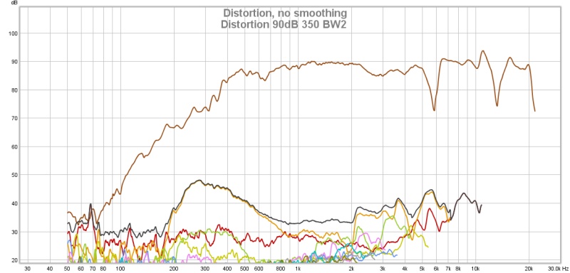
That appears to be only real drawback of using cone drivers wider than a wavelength of the upper frequency desired, as XRK mentioned it is a reflection cancellation at the driver and throat. PEQ can "fix" the cancellation to some extent, since the primary dip remains at the same frequency regardless of listening angle.Have you guys worked out a solution for the suckouts at 6k and 14k?
The dip is a function of the cone diameter and throat exit diameter, rather than horn geometry.
Of interest, yesterday I tried using a damping "O" ring of felt on a two inch (50mm) round entrance horn between the TC9 driver (nominally 3.5") and horn flange. The TC9 requires a standoff ring around the surround to keep it from hitting the mounting flange, a 3/16 (4mm) deep 3" (76mm) inside diameter plastic pipe around the surround works well as a standoff. The TC9 cone diameter is 2.5" (62mm), though the "effective" cone diameter including 1/2 the surround is 2 11/16 (68mm).
I expected the damping ring to reduce the dip, but the opposite result occurred, the damping made the dip 3 dB deeper, and wider!
Using a 2" to 1.4"(39mm) adapter to reduce the throat size increased the -5dB cancellation dip another 10 dB (!) to an unacceptable 15 dB hole, dropping from 5.6kHz to 4.9kHz. The frequency reduction and depth of the nulls indicates that the cone diameter should not be much larger than the horn throat to avoid the problem.
Bushmeister's smaller diameter driver using a 1.4" (39mm) throat ends up with a near identical dip as the TC9 on a 2", even though the horns used are quite different. A closer match of the throat entrance to cone diameter would reduce the dip, but as the excursion of little "full range" drivers seems limited to around 2.5mm, also comes with a reduction of SPL potential.
Art
Attachments
I have not delved into REW enough to know whether it automatically adjusts delay on each measurement, in which case the acoustic center (and phase) are already corrected for each polar measurement. I'm still primarily using Smaart, which requires the delay to be set for each measurement for accurate phase response. Art
There is a pretty good on-line manual for REW here:
REW Help Index
The specifics of the t=0 for the measurement and how minimum phase is calculated are actually discussed in more detail within the Help dialog of the installed program itself.
Here is an excerpt from the program's help utility under 'Impulse Graph', it is flexible and you can either have it automatically calculate the delay based on minimum phase assumptions or manually adjust based on time, distance, or samples. I highlighted the relevant text below.
Impulse Controls
The control panel for the Impulse graph has these controls:
The impulse response may be plotted with or without normalisation to its peak value according to the setting of the Plot Normalised control. When normalised plotting is selected the peak will be at 100% or 0dBFS.
If Show points when zoomed in is selected the individual points that make up the response are shown on the graph when the zoom level is high enough for them to be distinguished.
The response may be plotted inverted according to the setting of the Invert impulse control. Note that this has no effect when the Y axis is set to dB FS. If the soundcard you are using inverts its inputs that can be corrected using the Invert checkbox in the Soundcard Preferences Input Channel controls.
Generate Minimum Phase will produce a minimum phase version of the measurement using the current IR window settings. The minimum phase impulse then shows the response of a system having the same frequency response as the measurement but with the lowest phase shift such a system could have. This control also activates minimum and excess phase and group delay traces on the SPL & Phase and GD graphs respectively.
Note that the IR window settings are important as the minimum phase response is derived from the frequency (magnitude) response of the measurement, which in turn is affected by the IR window settings. If the window settings are subsequently changed Generate Minimum Phase should be used again to reflect the new settings. Note also that the shape of the left side window (the window applied before the peak) affects the minimum phase result, a rectangular window will produce a response with lower phase shift than, for example, a Hanning window.
If the system being measured was inherently minimum phase (as most crossovers are, for example) the minimum phase response is the same as removing any time delay from the measurement. Room measurements are typically not minimum phase except in some regions, mainly at low frequencies. For more about minimum and excess phase and group delay see Minimum Phase. Estimate IR Delay calculates an estimate of the time delay in the measurement by comparing it with a minimum phase version. The delay it calculates can be removed from the impulse response by pressing the Shift IR button on the panel shown after the delay is calculated.
The t=0 offset controls can be used to shift the zero time position by either a specified number of samples, a specified time or a specified distance. These controls can be used to manually remove measurement time delays or determine the correct delay to align measurements of different speakers or drive units. Note that shifting the impulse response will clear any spectrogram which had been generated as the plot would no longer be valid. If a loopback was used as a timing reference the System Delay figure (which can be viewed in the measurement Info panel) is shifted by the same amount as the zero time.
The Scale FR Peak control re-scales the impulse response to achieve a desired maximum SPL figure in the corresponding frequency response. This may be useful to rescale an imported impulse response.
ETC Smoothing is used to smooth the envelope (ETC) trace using a moving average filter of the duration specified in the spinner.
Of interest, yesterday I tried using a damping "O" ring of felt on a two inch (50mm) round entrance horn between the TC9 driver (nominally 3.5") and horn flange. The TC9 requires a standoff ring around the surround to keep it from hitting the mounting flange, a 3/16 (4mm) deep 3" (76mm) inside diameter plastic pipe around the surround works well as a standoff. The TC9 cone diameter is 2.5" (62mm), though the "effective" cone diameter including 1/2 the surround is 2 11/16 (68mm).
It may make it worse if the damping ring actually increased the distance from the throat to the cone center or throat to edge of where the end of the damping ring is. I was thinking that making a damping ring of width (radial dimension) equal to 1/4-wave of cancellation frequency and having it act as a stub to dampen the dip out.
A tuned "stub" can reduce a peak, the damping made the dip deeper 😉.It may make it worse if the damping ring actually increased the distance from the throat to the cone center or throat to edge of where the end of the damping ring is. I was thinking that making a damping ring of width (radial dimension) equal to 1/4-wave of cancellation frequency and having it act as a stub to dampen the dip out.
The graphs in post #249 all used the same exact distance from the cone to the throat mounting flange. The radial felt ring I used was about .5" (3" diameter standoff ring-2"diameter exit), a quarter wave of the 5.9kHz dip (.6") would only be .1" deeper.
I had not even considered the damping as a function of wavelength, just thought it might knock off some of the reflected energy from the outer portions of the driver, reducing the path length error that causes the cancellation.
To reverse engineer the data, you might consider the hard portion of the cone diameter (66mm) compared to the 50mm and 39mm throat sizes, and the resultant dip frequencies of 5.6kHz and 4.9kHz.
Art
We can buy magnets will it help Scan-Speak Magnets > Loudspeaker Freaks.
I have seen a few drivers that have an optional external magnet that can be slipped on with a shielding cup to hold it all together. I have also seen double ferrite magnet rings on drivers. I have an Alpair 7.3 with a removable second magnet. With it in place there is a small boost in Bl and slight reduction in Qts.
I am not sure you can do anything with the SB65 as it has a shielded shell over the Nd magnet already - and you would need an Nd ring magnet to really be able to give the existing Nd magnet a boost.
A tuned "stub" can reduce a peak, the damping made the dip deeper 😉.
The graphs in post #249 all used the same exact distance from the cone to the throat mounting flange. The radial felt ring I used was about .5" (3" diameter standoff ring-2"diameter exit), a quarter wave of the 5.9kHz dip (.6") would only be .1" deeper.
I had not even considered the damping as a function of wavelength, just thought it might knock off some of the reflected energy from the outer portions of the driver, reducing the path length error that causes the cancellation.
To reverse engineer the data, you might consider the hard portion of the cone diameter (66mm) compared to the 50mm and 39mm throat sizes, and the resultant dip frequencies of 5.6kHz and 4.9kHz.
Art
Perhaps this is a case where a flat BMR cone with flush (invisible) surround might work. If one could get the throat exactly to match the flat piston cone and not have any crevices for a cancellation peak to form. You still have the throat to throat distance, but then why doesn't a 1.4in comp driver with a phase plug have this problem?
A tuned "stub" can reduce a peak, the damping made the dip deeper
I guess that won't work then - I was hoping it smooths things either peaks or dips. It may depend on the Q of the stub.
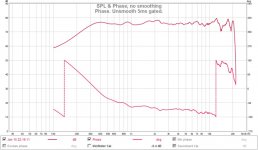
.....What do you think about these results? 😀
Attachments
OK, so a LOT of polishing, I tried various spacers - settled on some acoustic damping wool I have used in the past on baffles to reduce baffle diffraction.
I sloped the throat a little bit more, then lined the space between the surround, bezel and throat with a ring of it.
It has completely removed the cancellation.
Here is the step.
I sloped the throat a little bit more, then lined the space between the surround, bezel and throat with a ring of it.
It has completely removed the cancellation.
Here is the step.
Attachments

Right off to bed! I am so satisfied with the results of my toils - I'm gonna be afraid to cut the woofer taps in!!
- Home
- Loudspeakers
- Multi-Way
- A Bookshelf Multi-Way Point-Source Horn