Could you clue me in to where the N and S poles orient when attached to the frame.
You orient the magnets so that the poles attract (pull towards each other) across the gap. As to which side is north or south, it only effects polarity of the ribbon and isn't critical.
Casey
el' Ol-
I used 1018 which has .14-.2% carbon. Here is a breakdown of the standard SAE types of steel...
http://www.precisionsteel.com/tech_data/chemical.asp?n_cat_id=1
Casey
I used 1018 which has .14-.2% carbon. Here is a breakdown of the standard SAE types of steel...
http://www.precisionsteel.com/tech_data/chemical.asp?n_cat_id=1
Casey
A long overdue progress report..mainly due to the long overdue progress 😀 .
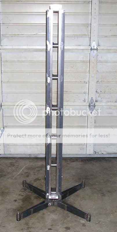
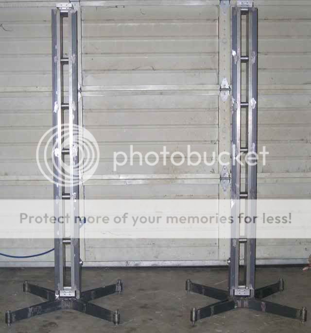
As I mentioned earlier, I decided to make some stands so that the ribbons were self supporting. This would give me a lot more flexibility with baffle design. Seemed fairly straight forward at the time 😉 . First obstacle was coming up with a design that would safely support the heavy ribbons. They had to be strong and stable..not so easy with such a top heavy load. Once I formulated a game plan I then needed to get the material. I had been hoarding a bunch of 1/4" x 2 1/4" pieces of hot rolled flat bar that were "end cuts" that had been given to me. Problem was they were all 6"-8" long. The first order of business was to weld these pieces together and cut them to size..thats one weekend down. Over the next couple of weekends I fabricated the bases, and cut the pieces for the saddle bracket...
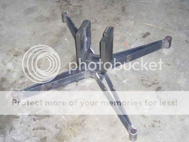
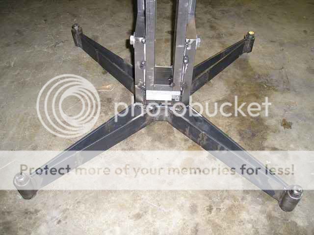
The upright pieces are just sitting on the base for the picture. The pieces of pipe on the leg ends are to hold levelers, and the pieces of 1/4" steel welded to the saddle uprights are spacers so the bracket clears the angle iron on the ribbon frames..so far so good. I mounted the bracket parts to the ribbon frame, cut the ends square, then welded the plate that act as the contact point between the bracket and base. My next move turned out to be a huge mistake...I unbolted the bracket to make welding on the base easier. In the process of welding the bracket it warped...a lot 😡 . My carefully measured and cut saddle was now over an 1/8" too narrow at the top, and wasn't even close to fitting. My first attempt at correcting this involved a wedge and a sledge hammer..the stand laughed at me. In disgust of my self imposed dilemma I decided to walk away and think about it. The next attempt was to modify a automotive scissor jack to fit in the gap to spread it..the jack screw snapped before the bracket budged (at least I know I've got the strength category covered). The solution was a time consuming one. I cut out the spacers and milled a taper opposite of the warp, and ground in a taper to match to clear the angle iron....finally a vertical ribbon...
I welded in nuts at the bottom of the pipe sections for leveling, some bolts are standing in for now until I make some nicer ones. This is the side the wire goes to the terminal block with a hole drilled for access, you can also see 1 of the 1/2"-13 bolts holding it to the frame. A 1/4"-28 screw goes through the angle iron into bracket on the front....
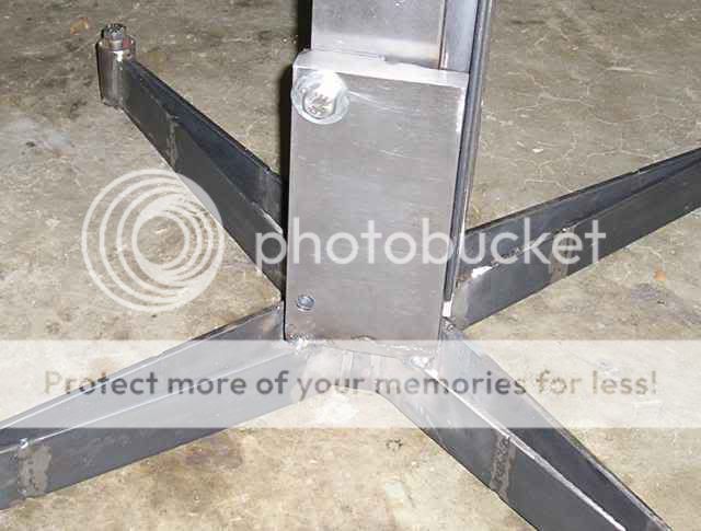
This is the back...
Mission accomplished . As my brother put it, you could climb the thing it's so stable. If you thump it, it vibrates around 3-5hz.
I hope to have the second stand completed next weekend..barring any more stupidity on my part 😀 .
Casey
As I mentioned earlier, I decided to make some stands so that the ribbons were self supporting. This would give me a lot more flexibility with baffle design. Seemed fairly straight forward at the time 😉 . First obstacle was coming up with a design that would safely support the heavy ribbons. They had to be strong and stable..not so easy with such a top heavy load. Once I formulated a game plan I then needed to get the material. I had been hoarding a bunch of 1/4" x 2 1/4" pieces of hot rolled flat bar that were "end cuts" that had been given to me. Problem was they were all 6"-8" long. The first order of business was to weld these pieces together and cut them to size..thats one weekend down. Over the next couple of weekends I fabricated the bases, and cut the pieces for the saddle bracket...
The upright pieces are just sitting on the base for the picture. The pieces of pipe on the leg ends are to hold levelers, and the pieces of 1/4" steel welded to the saddle uprights are spacers so the bracket clears the angle iron on the ribbon frames..so far so good. I mounted the bracket parts to the ribbon frame, cut the ends square, then welded the plate that act as the contact point between the bracket and base. My next move turned out to be a huge mistake...I unbolted the bracket to make welding on the base easier. In the process of welding the bracket it warped...a lot 😡 . My carefully measured and cut saddle was now over an 1/8" too narrow at the top, and wasn't even close to fitting. My first attempt at correcting this involved a wedge and a sledge hammer..the stand laughed at me. In disgust of my self imposed dilemma I decided to walk away and think about it. The next attempt was to modify a automotive scissor jack to fit in the gap to spread it..the jack screw snapped before the bracket budged (at least I know I've got the strength category covered). The solution was a time consuming one. I cut out the spacers and milled a taper opposite of the warp, and ground in a taper to match to clear the angle iron....finally a vertical ribbon...
I welded in nuts at the bottom of the pipe sections for leveling, some bolts are standing in for now until I make some nicer ones. This is the side the wire goes to the terminal block with a hole drilled for access, you can also see 1 of the 1/2"-13 bolts holding it to the frame. A 1/4"-28 screw goes through the angle iron into bracket on the front....
This is the back...
Mission accomplished
. As my brother put it, you could climb the thing it's so stable. If you thump it, it vibrates around 3-5hz.I hope to have the second stand completed next weekend..barring any more stupidity on my part 😀 .
Casey
valveitude said:I will be fabricating what amounts to a pair of Christmas tree stands on steroids to support the the ribbons "free standing". This will allow me to play around with baffle design to my hearts content until I find the optimum size/shape. Casey
Wow! Wow! Wow! Your stands look well thought out, and very capable of keeping your ribbons standing through that Devil's rock and roll music...or even a California rock and roll earthquake. You can select different "feet" to spike into carpet, rubber for grip, nylon for easy sliding, or even wheels. All this steel for a 1 gram aluminum ribbon.
I used 0.125" aluminum sheet for the stand, about 18" x 30", and counter sunk screws that threaded right into the ribbon pole steel. Our floor is tile, so I glued on grey plastic that is hard enough to slide just a little..as well as protect from screw head scratching. Yep...just copied the Apogee base.
Hi LineSource-
The pointy tailed one has met his match with these bad boys 😀 . Having not done this before I was actually concerned that they wouldn't be stable enough. Between grand kids and nieces/nephews I was afraid that if they weren't rock solid a horrible accident could happen..I am no longer worried. If someone is strong enough to tip them over, they are strong enough to hold the weight.
Yep 😉
Damn skippy 🙂 . I have been surprised again and again when "shoring up" an already rigid speaker. My experience has been it can't be to stiff/heavy. a simple trick to prove this is to wedge something between the wall and back of a speaker. The difference this makes to the resolution of the micro-dynamics never ceases to amaze.
That was my first thought as well, but after thinking it through, I didn't think it would offer the stability I needed. That, and the key to the Apogee stand is the slight tilt backwards. Since I don't know what my optimum angle is yet I didn't feel comfortable committing to one. All that aside the Apogee's are no where near as rigid as my setup..and I'm not done yet. My room is too small to place them as far from the back wall as I would like, so I plan to have a sand filled cylinder ( I'm thinking a 6"diameter section of PVC) about a foot behind the ribbon. This will attach to the top via another bracket. This will spread the near wall reflection and act as a fifth foot. I don't plan to do this until the rest of the system and it's placement is worked out. In the mean time I will just have the attachment points done.
Casey
...and very capable of keeping your ribbons standing through that Devil's rock and roll music..
The pointy tailed one has met his match with these bad boys 😀 . Having not done this before I was actually concerned that they wouldn't be stable enough. Between grand kids and nieces/nephews I was afraid that if they weren't rock solid a horrible accident could happen..I am no longer worried. If someone is strong enough to tip them over, they are strong enough to hold the weight.
You can select different "feet" to spike into carpet, rubber for grip, nylon for easy sliding, or even wheels
Yep 😉
All this steel for a 1 gram aluminum ribbon.
Damn skippy 🙂 . I have been surprised again and again when "shoring up" an already rigid speaker. My experience has been it can't be to stiff/heavy. a simple trick to prove this is to wedge something between the wall and back of a speaker. The difference this makes to the resolution of the micro-dynamics never ceases to amaze.
Yep...just copied the Apogee base.
That was my first thought as well, but after thinking it through, I didn't think it would offer the stability I needed. That, and the key to the Apogee stand is the slight tilt backwards. Since I don't know what my optimum angle is yet I didn't feel comfortable committing to one. All that aside the Apogee's are no where near as rigid as my setup..and I'm not done yet. My room is too small to place them as far from the back wall as I would like, so I plan to have a sand filled cylinder ( I'm thinking a 6"diameter section of PVC) about a foot behind the ribbon. This will attach to the top via another bracket. This will spread the near wall reflection and act as a fifth foot. I don't plan to do this until the rest of the system and it's placement is worked out. In the mean time I will just have the attachment points done.
Casey
Real nice, Are you going to run these with a transformer or a high current amp. Though they are presumable quite efficient you will have a hear short for a load. I cannot wait till you finish these things. You have any vacation coming up. Tad
Hi Tad,
Thanx.
Initially, at least, I will use a transformer. That doesn't bother me really. A high quality autoformer shouldn't be a big deal to make.
Approx. 1/2 ohm load, and around 97-103 dB @ 1 watt/meter according to the math and depending on foil thickness.
I know at least one other person that shares the sentiment 😀 .
Casey
Real nice
Thanx.
Are you going to run these with a transformer or a high current amp.
Initially, at least, I will use a transformer. That doesn't bother me really. A high quality autoformer shouldn't be a big deal to make.
Though they are presumable quite efficient you will have a hear short for a load.
Approx. 1/2 ohm load, and around 97-103 dB @ 1 watt/meter according to the math and depending on foil thickness.
I cannot wait till you finish these things.
I know at least one other person that shares the sentiment 😀 .
Casey
I've said it before about your projects, I'll say it again:
Wow. Well-engineered. Shame about the mistake, but that's how we learn, isn't it? You'll have it perfected by the time you've finished- going into production? 😀
I only hope that my projects (Curvy Changs, Valve amps and an Idler TT- Bought the materials for the Ladegaard arm now) go as well.
James
Wow. Well-engineered. Shame about the mistake, but that's how we learn, isn't it? You'll have it perfected by the time you've finished- going into production? 😀
I only hope that my projects (Curvy Changs, Valve amps and an Idler TT- Bought the materials for the Ladegaard arm now) go as well.
James
Hi James-
Unfortunately yes 😉. That was one lesson that I won't be forgetting any time soon..the deeper the cut , the longer the memory 😀. All told , between the disgust (along with the need to walk away), and the time figuring out and implementing the solution, I figure that screw-up cost me a month plus. On the next stand I'll put a piece of .005" shim stock between the saddle pieces and ribbon frame, and weld the whole thing while bolted up. The part that really torques me is that this was the original plan with the first stand, but I forgot the shim stock when I assembled it and was to lazy to take it back apart to put it in. The rest is history.
I have little doubt that it will James. Thats the beauty of diy. If you screw up a piece of the project you can either redo that part, or build the next piece to fit the screw up...can't do that in production, but with a one-off no prob
I hope you share your progress with us.
Casey
Shame about the mistake, but that's how we learn, isn't it?
Unfortunately yes 😉. That was one lesson that I won't be forgetting any time soon..the deeper the cut , the longer the memory 😀. All told , between the disgust (along with the need to walk away), and the time figuring out and implementing the solution, I figure that screw-up cost me a month plus. On the next stand I'll put a piece of .005" shim stock between the saddle pieces and ribbon frame, and weld the whole thing while bolted up. The part that really torques me is that this was the original plan with the first stand, but I forgot the shim stock when I assembled it and was to lazy to take it back apart to put it in. The rest is history.
I only hope that my projects (Curvy Changs, Valve amps and an Idler TT- Bought the materials for the Ladegaard arm now) go as well.
I have little doubt that it will James. Thats the beauty of diy. If you screw up a piece of the project you can either redo that part, or build the next piece to fit the screw up...can't do that in production, but with a one-off no prob
I hope you share your progress with us.
Casey
All is not roses however. While prepping the stand for its levelers while bolted to the frame, I had the frame laying across my saw and tail stand, and it slipped off the tail stand. Upon impacting the floor it shattered the top insulator block (I just sat the pieces on the ribbon for the pic). Oh well, it could have been a lot worse and I wasn't going to let it sour my mood. I'll whip up a replacement later.
Casey
Casey
Nah..the accompanying "thud" probably dislodged some dishes from the cupboard across the street though 😉
I'm lucky it landed the way it did. The Corion block gave it's life absorbing the impact preventing any other damage.
Casey
I'm lucky it landed the way it did. The Corion block gave it's life absorbing the impact preventing any other damage.
Casey
Very nice work
Valveitude
I like your design and quality of welding work. The concept looks very good. Possibly the best I have seen.
Personally I would prefer to see the ribbon frame insulated from the steel feet with 3- 4 inches of plastic as to keep the magnets away from the steel feet.
I suspect that you will find that the steel feet will drain some magnetic force from the lower part of the ribbon frame.
Jozua
Hi Jozua,
Of course I suppose it's possible, as is anything, but my modeling in FEMM as well as some simple experiments indicates that this isn't a problem. The lines of flux follows the path of least resistance (or more correctly reluctance)..the magnetic circuit connecting the gap where the magnets are pulling toward each other. If anything, I believe the stands may slightly (very slightly) increase the flux density at the bottom by providing another return path in parallel with the magnetic circuit.
I hope to find out soon 😉.
Casey
.....Personally I would prefer to see the ribbon frame insulated from the steel feet with 3- 4 inches of plastic as to keep the magnets away from the steel feet....
Of course I suppose it's possible, as is anything, but my modeling in FEMM as well as some simple experiments indicates that this isn't a problem. The lines of flux follows the path of least resistance (or more correctly reluctance)..the magnetic circuit connecting the gap where the magnets are pulling toward each other. If anything, I believe the stands may slightly (very slightly) increase the flux density at the bottom by providing another return path in parallel with the magnetic circuit.
I hope to find out soon 😉.
Casey
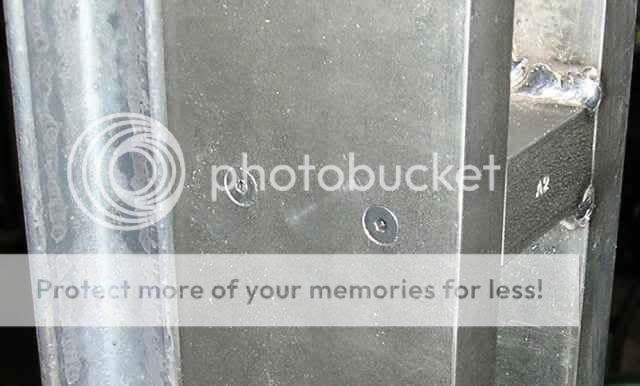
I'm curious as to how you are going to fix the magnets in the frame. With it welded up, I would think it's going to be quite a task.
Hi fperra,
The cross blocks are only welded on one side, the other rail is held on with screws so that the assembly can be split for magnet fastening.
Casey
I'm curious as to how you are going to fix the magnets in the frame. With it welded up, I would think it's going to be quite a task.
The cross blocks are only welded on one side, the other rail is held on with screws so that the assembly can be split for magnet fastening.
Casey
Jozua-
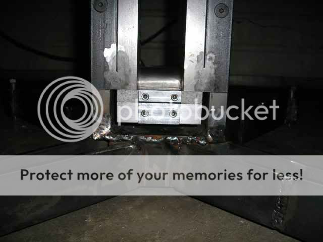
Here is a pic to better illustrate how the stand is in effect in parallel with the primary magnetic circuit. Visualize the stand rotated back 90 deg. and you can see that what little flux that is running through the relatively thin 1/4" plate that connects the saddle uprights to the stand is traveling the same direction as the flux in the circuit proper. Kind of like putting a 1 mega-ohm resistor in parallel with a 1 kilo-ohm one, in theory it lowers the total resistance, but not enough to really matter...
fperra-
Here is a closeup of one of the cross blocks showing the weld on one rail and the screws on the other...
Casey
- Status
- Not open for further replies.
- Home
- Loudspeakers
- Planars & Exotics
- A 60" Ribbon w/TL Loaded Extremis Hybrid