To help me with a little more info, when you look at a bar magnet with north facing up and south facing down, I would say the direct field is projecting up and down respectively. Would you agree or disagree with this?
Thanks.
Thanks.
To help me with a little more info, when you look at a bar magnet with north facing up and south facing down, I would say the direct field is projecting up and down respectively. Would you agree or disagree with this?
Heres your homework assignment 😀 ...
http://en.wikipedia.org/wiki/Magnetic_field
It is kind of ironic that the the direction of field rotation reminder, using the thumb and first two fingers, just happened to be in that little wiki you suggested.
Have you ever seem any reference to a ribbon design such as yours using electromagnets instead of permanent rare earth type magnets. Considering the initial cost it might be a more frugal approach. Still waiting to hear your interpretaion as to the sound of this cool project. Tad
Have you ever seem any reference to a ribbon design such as yours using electromagnets instead of permanent rare earth type magnets. Considering the initial cost it might be a more frugal approach. Still waiting to hear your interpretaion as to the sound of this cool project. Tad
Looking good, Casey, can't wait to hear them when they're up and singing.
The early patents are great fun to explore and read. If you look into those for the earliest ribbon transducers back in the '20s, you'll see that a few call for electromagnets due to limits in magnet technology at the time. Erwin Gerlach's Electrodynamic loud-speaking apparatus (US Patent #1557356) is one that appears to be similar to what you're thinking of.Have you ever seem any reference to a ribbon design such as yours using electromagnets instead of permanent rare earth type magnets. Considering the initial cost it might be a more frugal approach. Still waiting to hear your interpretaion as to the sound of this cool project. Tad [/B]
OK..I'm a patient man, but damn. I want to listen to them already!! Alas, it will be a few more weeks I'm afraid.
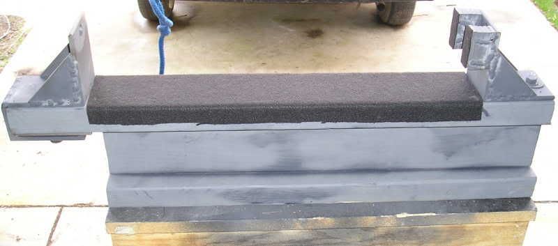
Finishing the stands. I neither enjoy, or am particularly good at finish work. I do manage to get acceptable results eventually though. I finally finished one stand this weekend (minus the spikes)...
The other one is about half done. I know I will be looking at these things a l-o-n-g time so I can't take to many short cuts with them.
Hopefully I'll have a more interesting update soon.
Casey
Getting close now 😀
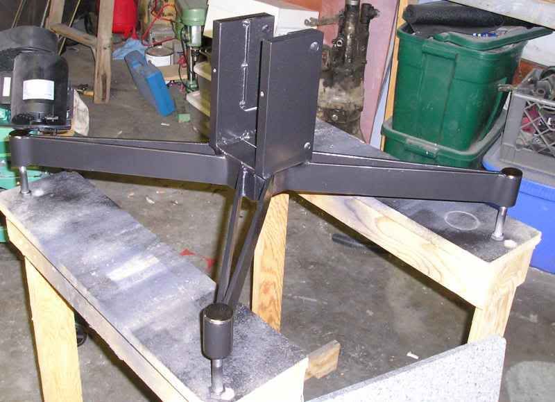
I finished the other stand last weekend so I was able to focus on the next hurdle...the jack needed to assemble the two halves once the magnets are laid in. It needs to handle both a lot of mass as well as force. After thinking about various temporary options I came to the realization there was no "quick fix" that I felt comfortable with. I've gone to far to muck up the most critical phase. A weekend of welding and cutting later...
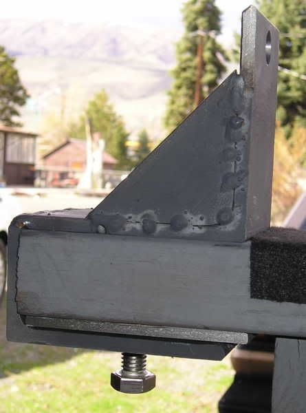
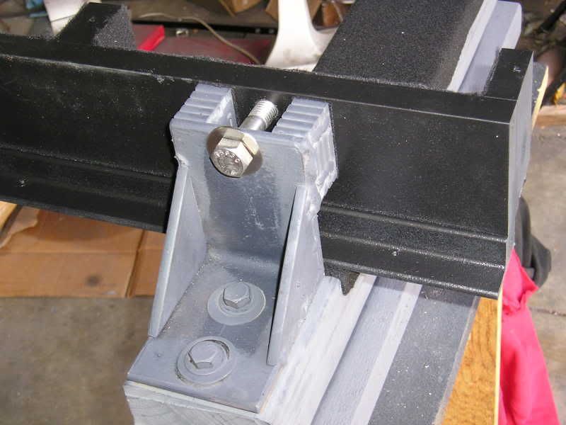
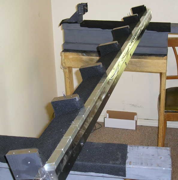
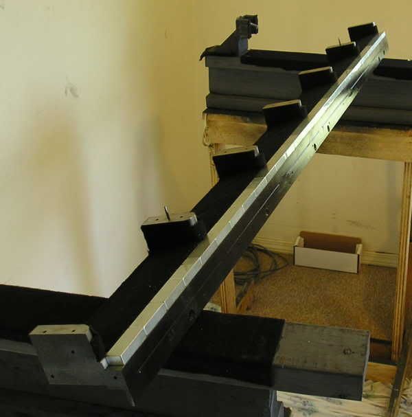
This is one of two. One end (on the right ) is bolted down to the wood "I" beam, and the other is removable and clamps on. Here is a close up of the fixed end...
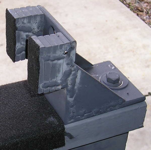
...and this is the movable end...
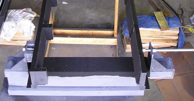
The rail with the cross blocks bolts to the fixed ends...
...and the movable ends are attached with thread rod to the other rail...
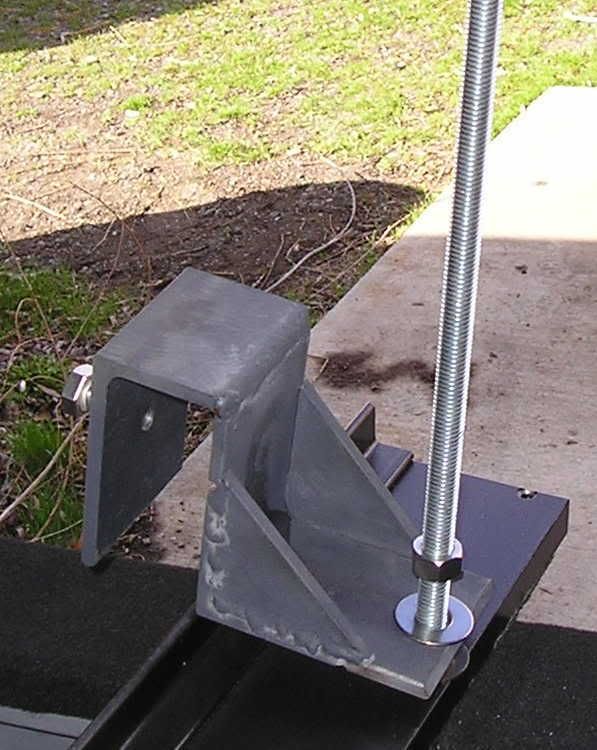
...which is then slid over the beam ends and tightened, and its ready to be jacked together...
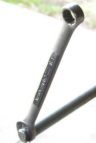
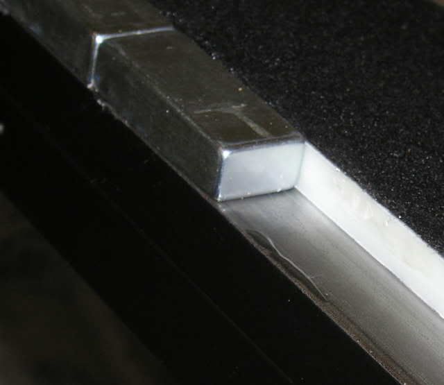
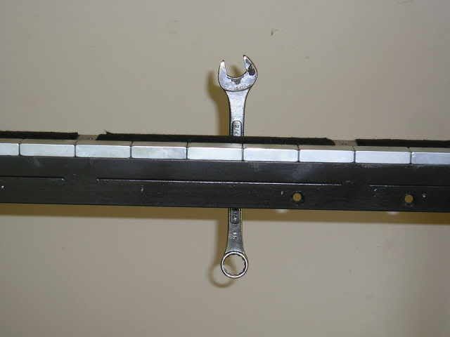
The ends of the of the thread rod are flattened to accept a 3/8" wrench so if the locknut on the rod slips I have a backup to prevent the rod from backing out....
I have a little minor tweaking to do yet, but I expect to lay in the magnets and do the final frame assembly next weekend.
Casey
I finished the other stand last weekend so I was able to focus on the next hurdle...the jack needed to assemble the two halves once the magnets are laid in. It needs to handle both a lot of mass as well as force. After thinking about various temporary options I came to the realization there was no "quick fix" that I felt comfortable with. I've gone to far to muck up the most critical phase. A weekend of welding and cutting later...
This is one of two. One end (on the right ) is bolted down to the wood "I" beam, and the other is removable and clamps on. Here is a close up of the fixed end...
...and this is the movable end...
The rail with the cross blocks bolts to the fixed ends...
...and the movable ends are attached with thread rod to the other rail...
...which is then slid over the beam ends and tightened, and its ready to be jacked together...
The ends of the of the thread rod are flattened to accept a 3/8" wrench so if the locknut on the rod slips I have a backup to prevent the rod from backing out....
I have a little minor tweaking to do yet, but I expect to lay in the magnets and do the final frame assembly next weekend.
Casey
Hey!! What happened?
Life got in the way 😉
I should have an update tonight or tomorrow.
Casey
[Austin Powers] YEAH BABY!! [/Austin Powers] 😀

What a beast.
The fine tuning of my jack turned out to be a big pain. As I had drilled the holes that the thread rod screws into the rails free hand the weren't perfectly square (duh). This caused the rod to be under a bind when the rails were close together. I decided to assign a rod to each hole and bend it straight after heating it with a torch. Unfortunately the weld shop is closed on Saturday so I had to wait to refill my O2 tank. After hooking the tank up I discovered that my regulator had gone south and I charged my line with the full 2000 psi of the tank. Fortunately I was able to shut down and bleed off without a "POP!!". After spending a day rebuilding a regulator I was finally able to bend the rods. I then installed and chamfered my alignment pins...

Then I went to work laying in magnets. Here is a shot showing my glue pattern...
Its hard to see, but thats super glue on the left and slow setting epoxy on the shoulder. As I mentioned a couple of times before, one of my rails has a slight bow in it that prevents it from laying flat when relaxed. I had about .05" clearance on the 2 end blocks. If the magnets were butted up to each other I was concerned that I wouldn't be able to pull it down flat when assembled so I placed a .0005" piece of shim stock down before I glued on the next magnet giving the space I needed...

I would then pull it out after the magnet was set. After laying in around half the magnets on the first rail I was curious to see if it had magnetized the rail significantly yet...
Yep 😀 . After all 30 magnets were glued to a side, I cleaned any glue off the surface and put a layer of packing tape down to insulate the nickel plating...
Then folded it over, trimmed it to the edge, then went back and puntured any air bubbles so that it layed flat...
After gluing all 60 magnets down, it was time for the moment of truth. My jacks worked a treat..in fact I don't see how I could of controlled the assembly without them. The force was intense. When I got to this point...

...I had to use a decent amount of force on the nut holding them apart to turn it. The only really nervous point was when they were the last 1/4" apart. At this point the magnets were pulling harder than the cross blocks and was toeing in slightly. Fortunately the pins did there job, and as soon as the lower edge of the cross block made contact it righted itself and aligned perfectly. I can't over state how freaking powerful the force I harnessed is. When I was test assembling them I had to use 2 clamps at each end to overcome the bowing of the rail to screw it down flat...when it came together it pulled itself flat!! I then mounted my end blocks for the final time...
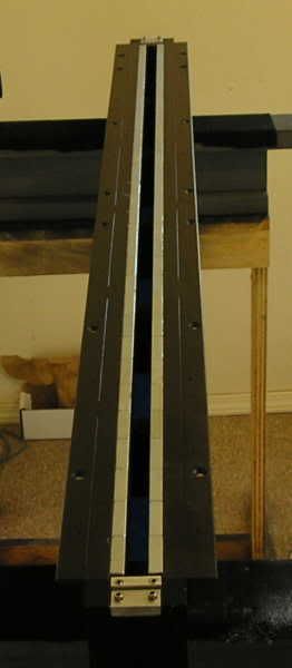
One completed motor assembly...
It took approximately four hours to assemble, and I feel like I have been beat up. I'm literally sore from my feet to my neck after wrestling with these magnets. I'll be waiting a few days to recover before tackling the second one.
One final point for now. Any concens about the ancillary steel (mounting flange and stands) "draining" any of the magnetic flux has been put to bed. I experimented with my shim stock and a razor blade, and I could detect NO residual magnetism anywhere in the frame...the energy of the magnets is completely harnessed in the gap.
Casey
What a beast.
The fine tuning of my jack turned out to be a big pain. As I had drilled the holes that the thread rod screws into the rails free hand the weren't perfectly square (duh). This caused the rod to be under a bind when the rails were close together. I decided to assign a rod to each hole and bend it straight after heating it with a torch. Unfortunately the weld shop is closed on Saturday so I had to wait to refill my O2 tank. After hooking the tank up I discovered that my regulator had gone south and I charged my line with the full 2000 psi of the tank. Fortunately I was able to shut down and bleed off without a "POP!!". After spending a day rebuilding a regulator I was finally able to bend the rods. I then installed and chamfered my alignment pins...
Then I went to work laying in magnets. Here is a shot showing my glue pattern...
Its hard to see, but thats super glue on the left and slow setting epoxy on the shoulder. As I mentioned a couple of times before, one of my rails has a slight bow in it that prevents it from laying flat when relaxed. I had about .05" clearance on the 2 end blocks. If the magnets were butted up to each other I was concerned that I wouldn't be able to pull it down flat when assembled so I placed a .0005" piece of shim stock down before I glued on the next magnet giving the space I needed...
I would then pull it out after the magnet was set. After laying in around half the magnets on the first rail I was curious to see if it had magnetized the rail significantly yet...
Yep 😀 . After all 30 magnets were glued to a side, I cleaned any glue off the surface and put a layer of packing tape down to insulate the nickel plating...
Then folded it over, trimmed it to the edge, then went back and puntured any air bubbles so that it layed flat...
After gluing all 60 magnets down, it was time for the moment of truth. My jacks worked a treat..in fact I don't see how I could of controlled the assembly without them. The force was intense. When I got to this point...
...I had to use a decent amount of force on the nut holding them apart to turn it. The only really nervous point was when they were the last 1/4" apart. At this point the magnets were pulling harder than the cross blocks and was toeing in slightly. Fortunately the pins did there job, and as soon as the lower edge of the cross block made contact it righted itself and aligned perfectly. I can't over state how freaking powerful the force I harnessed is. When I was test assembling them I had to use 2 clamps at each end to overcome the bowing of the rail to screw it down flat...when it came together it pulled itself flat!! I then mounted my end blocks for the final time...
One completed motor assembly...
It took approximately four hours to assemble, and I feel like I have been beat up. I'm literally sore from my feet to my neck after wrestling with these magnets. I'll be waiting a few days to recover before tackling the second one.
One final point for now. Any concens about the ancillary steel (mounting flange and stands) "draining" any of the magnetic flux has been put to bed. I experimented with my shim stock and a razor blade, and I could detect NO residual magnetism anywhere in the frame...the energy of the magnets is completely harnessed in the gap.
Casey
Casey, Now that you have one together what do you figure the total unit weighs.
Do you already have the TL unit built or must it be constructed also? I think it might be time for a cold one.
One to go. TAD
Do you already have the TL unit built or must it be constructed also? I think it might be time for a cold one.
One to go. TAD
TAD-
My brother who helped during assembly and I had a bit of a discussion over this. When I added things up in my head I came up with around 170 lbs. without the stand..he says it felt like more when we carried it to the living room. Anyway, with the stand mounted it's well over 200 lbs.
The TL is nothing more than a design at this point. I still have a lot of road to cover.
fperra-
Will do..thanx.
Casey
Casey, Now that you have one together what do you figure the total unit weighs.
My brother who helped during assembly and I had a bit of a discussion over this. When I added things up in my head I came up with around 170 lbs. without the stand..he says it felt like more when we carried it to the living room. Anyway, with the stand mounted it's well over 200 lbs.
Do you already have the TL unit built or must it be constructed also? I think it might be time for a cold one.
The TL is nothing more than a design at this point. I still have a lot of road to cover.
fperra-
If you need more ribbom material, let me know.
Will do..thanx.
Casey
Congrats on the completion of the first motor! There are no doubt alot of observers like me who are rooting for you and share that sentiment. You are doing a great job documenting this build, and I'm sure it will be one of the definitive resources for future builders.
Regards,
David
Regards,
David
Congratulations, Casey. Very well thought-through procedure, which shows from how smoothly it went.
What amplification are you going to be using?
What amplification are you going to be using?
Casey, You do know I am going to have to make a pair of these. Do you hire out by the hour?
When all is over please publish some of the things you would NOT have done the second time around. Would be a big help. Tad
When all is over please publish some of the things you would NOT have done the second time around. Would be a big help. Tad
gtforme00-
Thank you David
jrevillug-
Again, thanx 😉 Thought out it was. I can honestly say I spent more time thinking, and re-thinking, the final assembly process of the motor than any other aspect of the project. I knew that this was the most critical operation of the project. Screwing up here would really suck.
Initially what I have..a warmed over Fisher 800 tube receiver. I'll build an active crossover to go between it and some 250 watt NHT studio modules to drive the Extremis. Once I get my crossover point fine tuned and everything dialed in I am planning 2 different amps to try. 1) A push-pull class A amp based around the 6AS7, and a tube buffered UcD amp using just the modulator and finals of the Hypex module. Both designs will have the high pass built passively between stages eliminating the need for an external crossover. The bottom end amp will of course still need an external low pass. I have both designs simed in LtSpice but am stuck until I know the optimum crossover point.
tryonziess-
I do now 😀
How much money you got? Lets see. My first post was 10 months ago and I had a couple months design work before that. I figure I have around 500 hours into by now.
Will do. So far I'm enjoying my good fortune of success..of course thats subject to change 😉 .
Casey
Congrats on the completion of the first motor!...
Thank you David
jrevillug-
Congratulations, Casey. Very well thought-through procedure, which shows from how smoothly it went.
Again, thanx 😉 Thought out it was. I can honestly say I spent more time thinking, and re-thinking, the final assembly process of the motor than any other aspect of the project. I knew that this was the most critical operation of the project. Screwing up here would really suck.
What amplification are you going to be using?
Initially what I have..a warmed over Fisher 800 tube receiver. I'll build an active crossover to go between it and some 250 watt NHT studio modules to drive the Extremis. Once I get my crossover point fine tuned and everything dialed in I am planning 2 different amps to try. 1) A push-pull class A amp based around the 6AS7, and a tube buffered UcD amp using just the modulator and finals of the Hypex module. Both designs will have the high pass built passively between stages eliminating the need for an external crossover. The bottom end amp will of course still need an external low pass. I have both designs simed in LtSpice but am stuck until I know the optimum crossover point.
tryonziess-
Casey, You do know I am going to have to make a pair of these.
I do now 😀
Do you hire out by the hour?
How much money you got?
Lets see. My first post was 10 months ago and I had a couple months design work before that. I figure I have around 500 hours into by now.When all is over please publish some of the things you would NOT have done the second time around. Would be a big help. Tad
Will do. So far I'm enjoying my good fortune of success..of course thats subject to change 😉 .
Casey
The second motor is complete and in my living room 🙂 . I hadn't realized how up tight I was over the assembly until it was finished. After finishing the second frame it was like a huge exhale. Everything from this point on is reversible, if I screw up I can do it again.
I spent the better part of the remainder of the weekend thinking about the next move. I have decided to go ahead with a conventional corrugated ribbon at first, so my next move is to set up a cutting table and crimper for the foil.
Casey
I spent the better part of the remainder of the weekend thinking about the next move. I have decided to go ahead with a conventional corrugated ribbon at first, so my next move is to set up a cutting table and crimper for the foil.
Casey
Those look great!
There's just something awesome about a pair of speakers that instill a bit of fear of severe injury.
- JP
There's just something awesome about a pair of speakers that instill a bit of fear of severe injury.
- JP
magnificent
Hi Casey
I have following this thread ever since you took delivery of your "back beaking pile of steel & big ol' pile of scary magnets"
This is without a doubt one of the best examples of DIY that I have seen in a very long time.
Probably what makes this project unique, is the level of mechanical engineering that has been involved.
Every few days I check back on this site, and make a point to see if you have made any progress.
I am certain that you have a huge number of people watching and waiting.
I wish you all the very best success with this project, and I am sure that you will be richly rewarded.
Cant wait to see the completed units!!
Best Regards
George.
- Status
- Not open for further replies.
- Home
- Loudspeakers
- Planars & Exotics
- A 60" Ribbon w/TL Loaded Extremis Hybrid