Now you got me interested again..
Valveitude
You got me interested again in my own DIY ribbonspeakers project so hopefully I can post some pictures soon. I taking leave 4 a month so let's see how far i can get.
My gut feeling is you going to loose some magnetic power to the lower stands but hopefully I am wrong. I will not be surprised if the whole stand becomes magnetic in time.
Jozua
I don't know..maybe I can glue it  ...
...

Like I said, it could have been much worse, but the insulator block absorbed the bulk of the blow. I spent much of Saturday fabricating a new block. Since I made the first four together, making one took about as long as making four. Oh well..it's done now, all is well...

Now that the ribbon frame is structurally complete and fitting together, it's time to go backwards...
I will now detail and paint everything in preparation of laying in the magnets. I still need to drill the frames for an index pin before I split them though.
Onward...
Casey
...
Like I said, it could have been much worse, but the insulator block absorbed the bulk of the blow. I spent much of Saturday fabricating a new block. Since I made the first four together, making one took about as long as making four. Oh well..it's done now, all is well...
Now that the ribbon frame is structurally complete and fitting together, it's time to go backwards...
I will now detail and paint everything in preparation of laying in the magnets. I still need to drill the frames for an index pin before I split them though.
Onward...
Casey
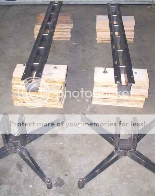
Another weekend and some progress..as usual not as much as I had hoped for 😉
This was a weekend of more drilling and tapping. Rather than grunting the frames up to the drill press I decided to do the work with a hand held drill. First order of business was to drill for my indexing pins. These were the only truly critical holes so I made a drill block to keep them true...
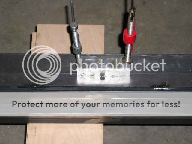
The next step waited 'till now for the simple reason it took me awhile to figure out how I wanted to drill out the angle iron for mounting. I decided on a scheme where I bolt the baffles on the backside with pan heads and screw down the face plate from the front. First I laid out my pattern...
Then I drilled and counter-sunk the holes for the through bolts and dilled and tapped the 6-32 holes for the face plate...
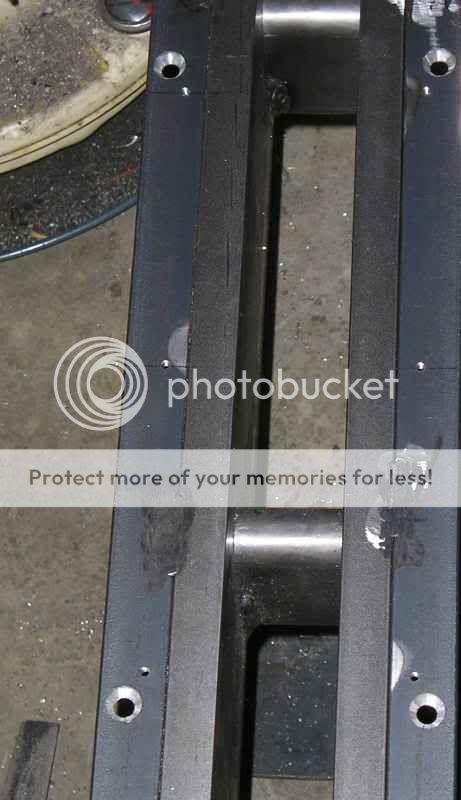
...a LOT...
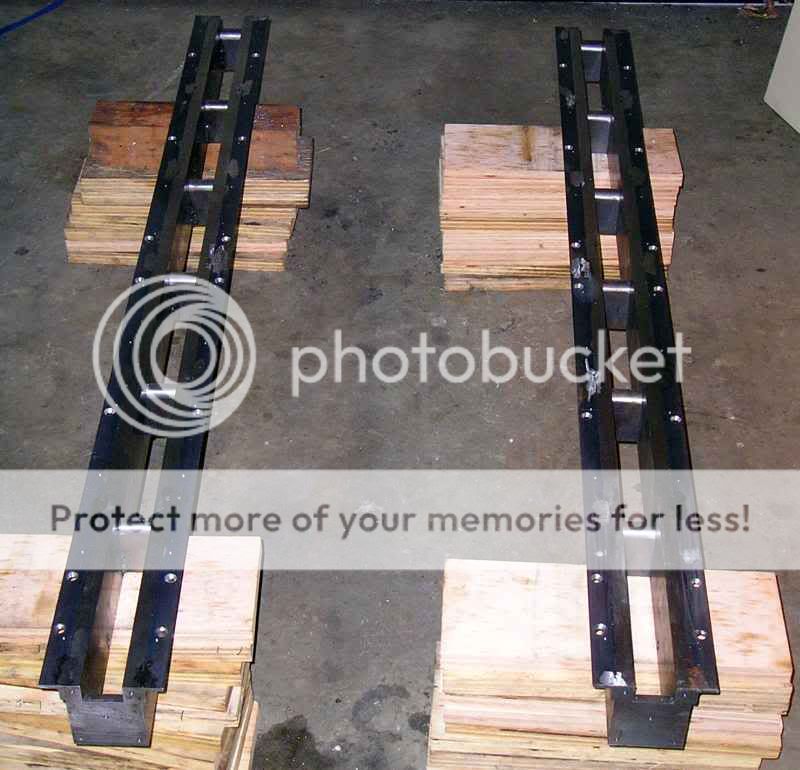
A total of 12 through holes and 48 tapped 6-32 holes. If I were to do it again, I most certainly would have gone up to an 8-32 screw...a 1/4" of hot rolled steel is asking a lot from a 6-32 tap. I managed to break 3 of them in the process, 2 of which I had to dig out then repair the hole with J-B Weld. Good times.
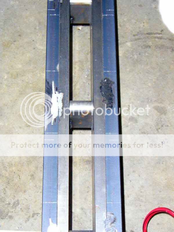
After that ordeal I was finally to the point where I could split the frames...

This is where the weekend ended. Next up..final prepping and acoustical treatment.
Casey
This was a weekend of more drilling and tapping. Rather than grunting the frames up to the drill press I decided to do the work with a hand held drill. First order of business was to drill for my indexing pins. These were the only truly critical holes so I made a drill block to keep them true...
The next step waited 'till now for the simple reason it took me awhile to figure out how I wanted to drill out the angle iron for mounting. I decided on a scheme where I bolt the baffles on the backside with pan heads and screw down the face plate from the front. First I laid out my pattern...
Then I drilled and counter-sunk the holes for the through bolts and dilled and tapped the 6-32 holes for the face plate...
...a LOT...
A total of 12 through holes and 48 tapped 6-32 holes. If I were to do it again, I most certainly would have gone up to an 8-32 screw...a 1/4" of hot rolled steel is asking a lot from a 6-32 tap. I managed to break 3 of them in the process, 2 of which I had to dig out then repair the hole with J-B Weld. Good times.
After that ordeal I was finally to the point where I could split the frames...
This is where the weekend ended. Next up..final prepping and acoustical treatment.
Casey
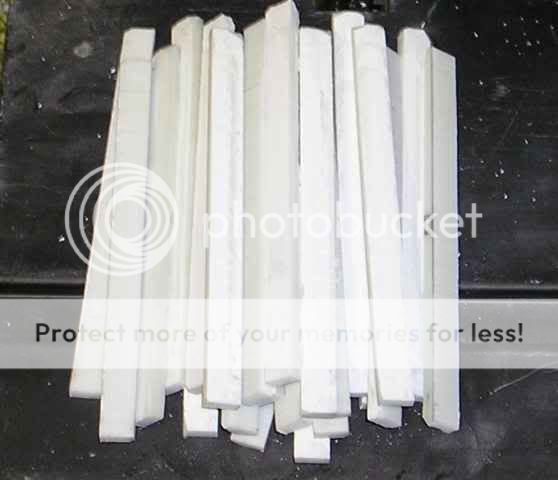
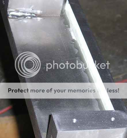
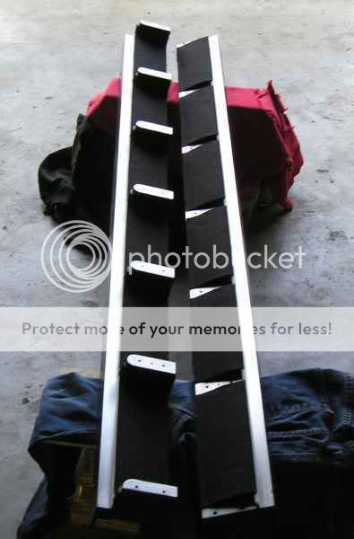
First order of business this weekend was grinding the welds and cleaning up the weld spatter. I then went to work on a magnet backer, a shoulder to mount the magnets against. I'm not comfortable with just a spot of super-glue holding the magnets in. I'm sure they would hold under normal circumstances, but if,God forbid, they were ever to fall I want a little more holding them back from the shock...super-glue is brittle. With the backer I will have 2 glue points. One with super-glue under the magnet, and the other with epoxy on the side. It should be much stronger with 2 shear planes.
I made my stock by rough cutting strips of Corian with the bandsaw, then milling down two sides. I ended up with 48 5" long pieces. Here are 24 of them...
I then cut and milled a piece of Corian to match the width of the magnets and made a spacing jig...
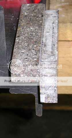
I clamped the pieces to the jig and spot glued the pieces in place with super-glue. I'm half way done with one rail here...
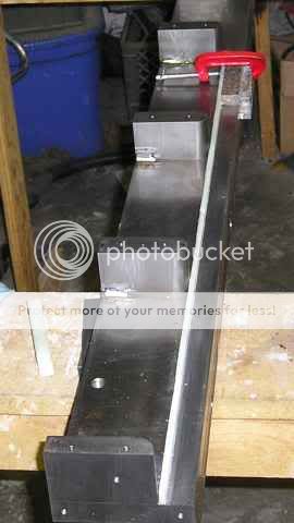
Once all the pieces were glued down I glued a fillet on the back side with epoxy. The apparent gap in the glue in this picture is a funky flash artifact (after seeing it I went out to check)...
I then repeated the process with the matching rail, then let them cure overnight. The next day I reassembled two halves...
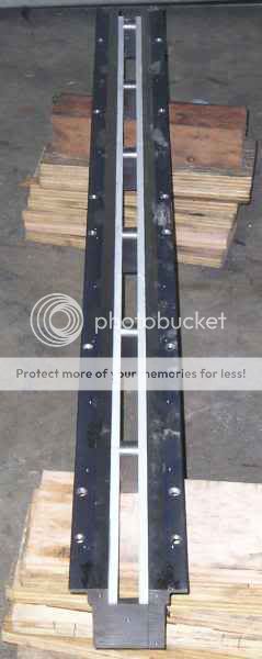
After I finish with the other frame I will do the final sanding and lay down a coat of primer. Then the frames will then be split one last time to lay in the Sorbothane and felt sound treatment.
Casey
I made my stock by rough cutting strips of Corian with the bandsaw, then milling down two sides. I ended up with 48 5" long pieces. Here are 24 of them...
I then cut and milled a piece of Corian to match the width of the magnets and made a spacing jig...
I clamped the pieces to the jig and spot glued the pieces in place with super-glue. I'm half way done with one rail here...
Once all the pieces were glued down I glued a fillet on the back side with epoxy. The apparent gap in the glue in this picture is a funky flash artifact (after seeing it I went out to check)...
I then repeated the process with the matching rail, then let them cure overnight. The next day I reassembled two halves...
After I finish with the other frame I will do the final sanding and lay down a coat of primer. Then the frames will then be split one last time to lay in the Sorbothane and felt sound treatment.
Casey
Finally a weekend with a satisfying amount accomplished 🙂
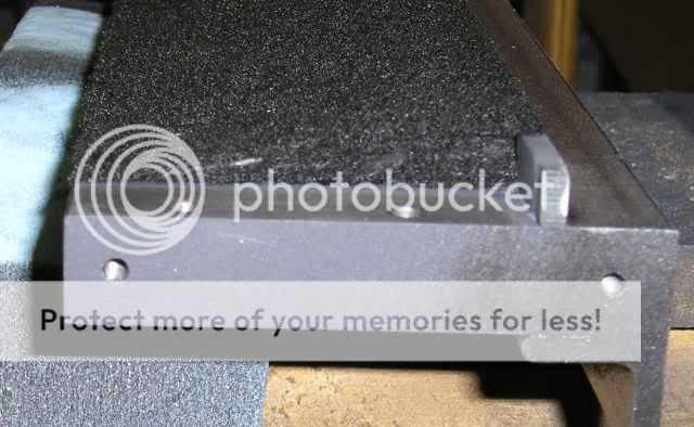
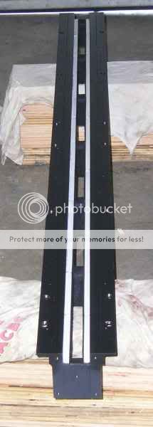
After I finished up the Corian shoulder on the other frame I did the final sanding, and primer/painted them. I didn't go crazy with the finish. The only part of the frame that will be visible when finished will be part of the sides, even then you would have to look behind the baffle. I painted them to protect the steel and give me an outline of the mount points of the cross-blocks. I then split them back apart and glued a piece of Sorbothane over the radius on the cross-blocks...

Then I put a layer of felt over it and the rest of the block after I cut notches to clear the shoulders...

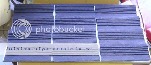
I then turned to the rest of the frame. I cut strips of felt to match the space between blocks in a progression of widths...

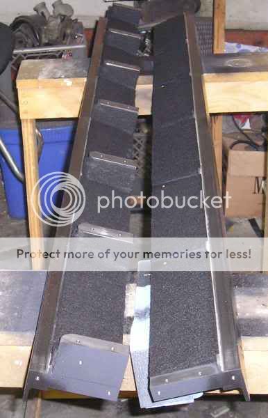
...which I then laminated together with one edge aligned forming a shallow wedge...

I then glued these between the cross-blocks with the thick side butted up to the shoulder. Once in place I then glued down one final piece of felt on to the top of the shoulder and wrapped the wedge...

 😀 I'm not too worried about early reflections making there way out intact.
Finally I reassembled to test the fit and to make sure nothing got pinched under a block during assembly...
This frame is now ready for the magnets. I still have the other to do yet, but the work is easy and repetitious so I should be able to get most of it done doing a little each night after work.
I have to admit to getting a little excited even though there is still considerable work to be done.
Now for a question for anybody to answer. My brain decided to eject a piece of rarely used data that I now need. Worse yet I can't find the reference. How do I orient the polarity of the magnets to make the top terminal "+", that is to say the terminal that causes a forward motion with a positive current relative to the other terminal? I swear I used to know this.
Casey
After I finished up the Corian shoulder on the other frame I did the final sanding, and primer/painted them. I didn't go crazy with the finish. The only part of the frame that will be visible when finished will be part of the sides, even then you would have to look behind the baffle. I painted them to protect the steel and give me an outline of the mount points of the cross-blocks. I then split them back apart and glued a piece of Sorbothane over the radius on the cross-blocks...
Then I put a layer of felt over it and the rest of the block after I cut notches to clear the shoulders...
I then turned to the rest of the frame. I cut strips of felt to match the space between blocks in a progression of widths...
...which I then laminated together with one edge aligned forming a shallow wedge...
I then glued these between the cross-blocks with the thick side butted up to the shoulder. Once in place I then glued down one final piece of felt on to the top of the shoulder and wrapped the wedge...
😀 I'm not too worried about early reflections making there way out intact.Finally I reassembled to test the fit and to make sure nothing got pinched under a block during assembly...
This frame is now ready for the magnets. I still have the other to do yet, but the work is easy and repetitious so I should be able to get most of it done doing a little each night after work.
I have to admit to getting a little excited even though there is still considerable work to be done.
Now for a question for anybody to answer. My brain decided to eject a piece of rarely used data that I now need. Worse yet I can't find the reference. How do I orient the polarity of the magnets to make the top terminal "+", that is to say the terminal that causes a forward motion with a positive current relative to the other terminal? I swear I used to know this.
Casey
It doesn't matter. Just make sure both speakers are the same. How you hook up the speaker wires will determine the polarity.
Cool project! I can't wait to see the results, but he WAF cannot be high on those, hehe...
-Justin
-Justin
What you want is flemings Left-Hand Motor rule:
http://www.diracdelta.co.uk/science/source/f/l/flemings left hand rule/source.html
James
http://www.diracdelta.co.uk/science/source/f/l/flemings left hand rule/source.html
James
fperra-
True in that it will work either way, but I want the "+" on top 😉
despotic931-
Thanx..I guess the "WAF" would be determined by the "W" in question 😀
jrevillug-
That's it!! You da man...thanx.
Casey
It doesn't matter....
True in that it will work either way, but I want the "+" on top 😉
despotic931-
Cool project! I can't wait to see the results, but he WAF cannot be high on those, hehe...
Thanx..I guess the "WAF" would be determined by the "W" in question 😀
jrevillug-
What you want is flemings Left-Hand Motor rule:
http://www.diracdelta.co.uk/science...ule/source.html
That's it!! You da man...thanx.
Casey
jrevillug-
Apparently the ‘ol cerebellum dumped the whole folder 😉. Fleming’s Left Hand Rule is in fact what I had forgotten, but now I realize I can’t remember the direction of the magnetic field..is it South to North? In other words do I point to the North or South pole? I already caught one potential error. The current direction is “conventional”..in other words wrong, so I point to the negative terminal.
Guess it’s time to look into memory enhancement supplements 🙂.
Casey
Just place a wire between two magnets and connect a battery to the wire , and you will see!!

Koldby
Koldby
I don't mean to get off subject a little and look backwards but I have a couple questions that I can't seem to get any good answers to.
First off, congrats on the great looking project. Oddly enough this is something that would be right up my alley as I work in a metal fab shop!! The main question I can't find an answer to is dispersion or polar resonse. As we all know, certain drivers have certain vertical and horizontal characteristics. The polar response may be a non-issue as this is a line source. How will these react across 7-8 octaves in the horizontal field as it is a .5" element?
Thanks.
Casey, Have you performed any beta tests with your choice of adhesive for this project. The magnets that I purchased -- though not as large as the ones you are using -- exhibit remarkable polar attraction. I feel that it might be prudent to experiment with various adhesives prior to fastening the magnets to the frame. I have found that a catalyst activated urethane to be most reliable on hard metals such as you have. One other note you might consider is just how well the nickel plating has adhered to the base magnet. As you have probably already found out these little suckers have incredible attraction for each other and could pull free of the electroplating.
One question please. How do you determine what the maximum effective ribbon width can be for a given set of magnets. The field from my magnets seems to span 2 - 2.5 inches. Excellent work so far and thanks Tad
One question please. How do you determine what the maximum effective ribbon width can be for a given set of magnets. The field from my magnets seems to span 2 - 2.5 inches. Excellent work so far and thanks Tad
koldby-
That is plan "B" 😉.
goskers-
Thank you.
Actually my ribbon is .75". Dispersion is determined by freq vs. width of the driver. It's more or less 180 deg. until you reach 1/2 wavelength, thus a 1" tweeter starts to "beam" at around 10khz and a 1/2" around 20khz. I chose 3/4" as a happy medium between dispersion and surface area. When you go dipole your lower roll off point is limited by how wide your baffle is. Google Linkwitz Orion for an education on dipoles. On the vertical plane there is very little dispersion, hence the title "linesource".
tryonziess-
How well you have to mount the magnets is as much a function of the effectiveness of the magnetic circuit as anything. If you mount the magnets on a piece of wood for example you have nothing but the mount holding them from crashing into one another. If you have a low reluctance return path to complete the magnetic circuit (the reason for the insane amount of steel I used) then the pull is more or less equal on both sides of the magnet and you just need to keep the magnets from repelling each other on the same rail. Superglue has been used many times with success, but as I mentioned earlier, I feel more comfortable having a shoulder to epoxy to in addition to the superglue under the magnets.
I would download FEMM and model it. It's a freeware 2D magnetics modeling program. I think you will find 2-2.5" problematic. 2 things happen as you spread the gap. 1) the flux in the gap diminishes rapidly, and 2)(and this is the real problem) the lines of flux get less straight creating an increase in distortion as the ribbon travels through the non-linear magnetic field.
Thanx, and your welcome.
Casey
Just place a wire between two magnets and connect a battery to the wire , and you will see!!
That is plan "B" 😉.
goskers-
First off, congrats on the great looking project.
Thank you.
The main question I can't find an answer to is dispersion or polar resonse. As we all know, certain drivers have certain vertical and horizontal characteristics. The polar response may be a non-issue as this is a line source. How will these react across 7-8 octaves in the horizontal field as it is a .5" element?
Actually my ribbon is .75". Dispersion is determined by freq vs. width of the driver. It's more or less 180 deg. until you reach 1/2 wavelength, thus a 1" tweeter starts to "beam" at around 10khz and a 1/2" around 20khz. I chose 3/4" as a happy medium between dispersion and surface area. When you go dipole your lower roll off point is limited by how wide your baffle is. Google Linkwitz Orion for an education on dipoles. On the vertical plane there is very little dispersion, hence the title "linesource".
tryonziess-
Casey, Have you performed any beta tests with your choice of adhesive for this project. The magnets that I purchased -- though not as large as the ones you are using -- exhibit remarkable polar attraction. I feel that it might be prudent to experiment with various adhesives prior to fastening the magnets to the frame....
How well you have to mount the magnets is as much a function of the effectiveness of the magnetic circuit as anything. If you mount the magnets on a piece of wood for example you have nothing but the mount holding them from crashing into one another. If you have a low reluctance return path to complete the magnetic circuit (the reason for the insane amount of steel I used) then the pull is more or less equal on both sides of the magnet and you just need to keep the magnets from repelling each other on the same rail. Superglue has been used many times with success, but as I mentioned earlier, I feel more comfortable having a shoulder to epoxy to in addition to the superglue under the magnets.
One question please. How do you determine what the maximum effective ribbon width can be for a given set of magnets. The field from my magnets seems to span 2 - 2.5 inches.
I would download FEMM and model it. It's a freeware 2D magnetics modeling program. I think you will find 2-2.5" problematic. 2 things happen as you spread the gap. 1) the flux in the gap diminishes rapidly, and 2)(and this is the real problem) the lines of flux get less straight creating an increase in distortion as the ribbon travels through the non-linear magnetic field.
Excellent work so far and thanks Tad
Thanx, and your welcome.
Casey
Cut..cut..glue..glue. So went Saturday 🙂
On the first frame I cut and glued one section at a time, this go around I went the assembly line approach. Not only was this faster, it really gives an idea of the labor involved with such a "minor" step. First up was spending some quality time at the cutting board...

Then some fun with a bottle of "Tacky Glue"...
Finally applying the felt to the other frame...
Alas, this is as far as I got. The "past due" domestic chores ate up Sunday.
Next up is doing the finish work on the stands. I want to put the ribbons in the house as soon as I apply the magnets, and I don't want to have to wrestle the stands off and on later. Soon as thats done I go to work on the assembly jig to bring the 2 frame halves together in a controlled manner.
Casey
On the first frame I cut and glued one section at a time, this go around I went the assembly line approach. Not only was this faster, it really gives an idea of the labor involved with such a "minor" step. First up was spending some quality time at the cutting board...
Then some fun with a bottle of "Tacky Glue"...
Finally applying the felt to the other frame...
Alas, this is as far as I got. The "past due" domestic chores ate up Sunday.
Next up is doing the finish work on the stands. I want to put the ribbons in the house as soon as I apply the magnets, and I don't want to have to wrestle the stands off and on later. Soon as thats done I go to work on the assembly jig to bring the 2 frame halves together in a controlled manner.
Casey
valveitude said:jrevillug-
Apparently the ‘ol cerebellum dumped the whole folder 😉. Fleming’s Left Hand Rule is in fact what I had forgotten, but now I realize I can’t remember the direction of the magnetic field..is it South to North? In other words do I point to the North or South pole? I already caught one potential error. The current direction is “conventional”..in other words wrong, so I point to the negative terminal.
Guess it’s time to look into memory enhancement supplements 🙂.
Casey
😀
Me too.😕
My old GCSE Revision guide:
"Current: dc - this is always from + to -
Field: direction is always from N to S.
Force: depends on how the other two align."
So point to the south pole.
James
My old GCSE Revision guide:
"Current: dc - this is always from + to -
Field: direction is always from N to S.
Force: depends on how the other two align
Beauty..thank you James for looking that up for me 😉
So the south pole goes on the right side if I want "+" on top. Thats one less thing to think about.
Casey
I have a fairly dumb question. While thinking about the design of my upcoming ribbons I have run across a problem. Not being a magnetics expert, I am trying to figure out which configuration the magnets need to be placed in the circuit for functionality. The web offers some contradicting diagrams. I would think that the right hand rule, which you are essentially using what I would call the stray magnetic field comes into play to control and move the ribbon element. I have also seen the contrary which has the magnets strongest properties, the force coming directly from the north and south poles pointing towards the gap. Which one is correct?
Thinking about a cone type speaker says that the right hand rule, similar to a solenoid applies which has the 'stray field' controlling the element. I would think that a ribbon would be just the same but I am not sure.
Thanks.
Thinking about a cone type speaker says that the right hand rule, similar to a solenoid applies which has the 'stray field' controlling the element. I would think that a ribbon would be just the same but I am not sure.
Thanks.
- Status
- Not open for further replies.
- Home
- Loudspeakers
- Planars & Exotics
- A 60" Ribbon w/TL Loaded Extremis Hybrid