I know why the tweeter level doesn't agree. It's because I matched our measurements to the woofer level, but I measured two woofers and you measured one woofer. So it is not something wrong.
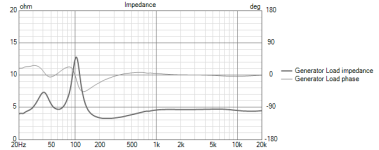
Sorry for the delay. Here is your impedance data. You can now simulate an accurate crossover 🙂
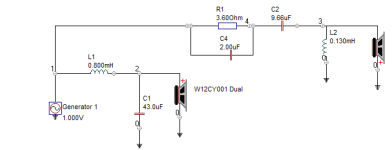
Note the frequency response and impedance for the W12CY001 is for dual parallel woofers so they can be treated as a single driver in simulation.
Note the frequency response and impedance for the W12CY001 is for dual parallel woofers so they can be treated as a single driver in simulation.
Attachments
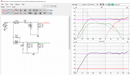
A quick crack at it myself. That bump around 1KHz is mostly unavoidable cabinet diffraction (but is pretty mild IMO).

Inverted null

Xover network.

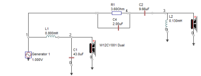
Below is another variation with a better inverse null, but also a bit more of that mid-bump.

Inverse Null.

Xover network.

Inverted null
Xover network.
Below is another variation with a better inverse null, but also a bit more of that mid-bump.
Inverse Null.
Xover network.
Attachments

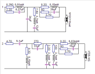

Nice! Which of those resistors are just to represent the series resistance of the inductors and capacitors and which are 'real' resistors?
In all shunted series LCR networks (one in the bass/mid branch, two in the tweeters') the resistors represent the total resistance.
So deduct the coil resistance (caps are presumed zero in practice) and calculate the "real" R value.
Perhaps stating the obvious, but also each individual coil in other positions has its' resistance shown by the R element, which is not "real".
So deduct the coil resistance (caps are presumed zero in practice) and calculate the "real" R value.
Perhaps stating the obvious, but also each individual coil in other positions has its' resistance shown by the R element, which is not "real".
The LCR parallel to the woofers on the last lowpass is preferable to the others. You can’t get the BSC correct with just standard topologies imho.
Of course it can be reworked. The point was that it can get complex fast (the crossover).
Plus this is based on a single-axis measurement only.
A proper full set of measurements (multi axis, near+far field, dual channel time aligned etc, as per book: https://kimmosaunisto.net/Software/VituixCAD/VituixCAD_Measurement_ARTA.pdf) is needed for a solid design.
Plus this is based on a single-axis measurement only.
A proper full set of measurements (multi axis, near+far field, dual channel time aligned etc, as per book: https://kimmosaunisto.net/Software/VituixCAD/VituixCAD_Measurement_ARTA.pdf) is needed for a solid design.
Last edited:

Which xover design are you using?I finally got back to them and found an error right away - the tweeters were not inverted in polarity while they should have been. In the meantime I built ZRT 2.5 and DXT MON 182. Both are now struggling to compete with this design…
I might have missed a trick here but your woofer crossover creates an ultra high frequency short for your amplifier with a path via the 0.3uF then 4.7uF cap to ground. This may or may not cause oscillation and low load issues for your amplifier
I was experimenting with another mic I have, also uncalibrated, but seems to be flatter than the previous one in high frequencies range. 1/12 smoothing. Tweeter resistor set at 1R5, to match closely the amounts of highs on DXT-MON-182. Some stuffing also added, it used to be very light before - just carpet tiles.
Attachments
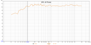
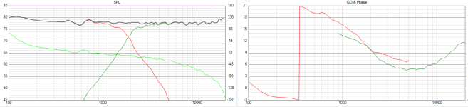
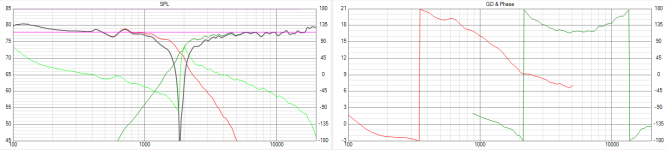
I recommend using a 5dB scale for this kind of thing. 10dB is too course because our ears are far more sensitive.
Your result looks pretty smooth. The only thing that bothers me is the 3 to 4dB broad hump between 4KHz to 10KHz. That is due to the waveguide.
I would recommend sticking the data I supplied in to your simulation and see how it looks, then you can make a few tweaks. Remember to delete one of the woofer because my data is for the pair already.
The Phase is not correct with this design TBH. IF I flip the polarity we do not see a deep null, just a droop.
Inverted Tweeter:
If you want to hear what these speakers can really do, it's time to build a new xover 🙂
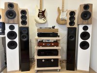
This looks lovely BTW!I finally got back to them and found an error right away - the tweeters were not inverted in polarity while they should have been. In the meantime I built ZRT 2.5 and DXT MON 182. Both are now struggling to compete with this design…
- Home
- Loudspeakers
- Multi-Way
- 8 Excel W12CY001 looking for a DIY project to fit in