Great!
Now, according to the phase... if the primaries are in parallel and the secondaries are in series....
Then I should either see double the voltage of a single transformer... or nothing at all, if the phases cancel out.... depending on the arrangement...
Problems might arrise if the wires aren't labeled... last I checked they weren't...
Any suggestions?
krazatchu said:Great!
Now, according to the phase... if the primaries are in parallel and the secondaries are in series....
Then I should either see double the voltage of a single transformer... or nothing at all, if the phases cancel out.... depending on the arrangement...
Problems might arrise if the wires aren't labeled... last I checked they weren't...
Any suggestions?
Hi,
You should already know this:
To determine phase:
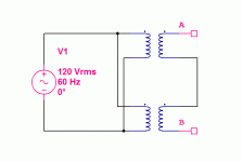
Connect one each of the secondaries together. Measure the voltage across A-B (in attached graphic).
Attachments
krazatchu said:[...]
The highest output voltage I could find was 110v... with a 220 primary, we use 220 in Korea...
To get 125VDC, I will need about 140VAC...
[...]
No way! 😱 You will get around 200V DC (unloaded) with a 140V transformer. 140V AC with center tap (70-0-70) will give you around +-100V DC. Or did I miss something?
You said the simulation suggested that +-125V would work. Did you check the dissipation in the output transistors and drivers? What does the impedance curve look like? Is the 30 ohms at resonace a dip or a peak? If it is a peak then drifting off the resonance by just a little would make your outputs and/or drivers blow if they haven't done that already.
A class D amplifier (UcD module maybe?) or resonant drive ciruit feels like a much better solution.
The limit for my design is ±100V for speakers, the SOA on the MJ21195/96 folds back above 80V.
For a capacitor (piezo)?
At ±125V?
I wouldn't do it.
With four pair of outputs and a 50-0-50 800VA transformer it will make a nice 400W/4W subwoofer amp.
If you want to try the piezo, then use an autoformer. At 28Khz an autoformer made from a 1mH inductor with 18ga will be fine.
For a capacitor (piezo)?
At ±125V?
I wouldn't do it.
With four pair of outputs and a 50-0-50 800VA transformer it will make a nice 400W/4W subwoofer amp.
If you want to try the piezo, then use an autoformer. At 28Khz an autoformer made from a 1mH inductor with 18ga will be fine.
Hmm..
I see, I just checked the SOA on the mj21193/94...
So, I will run the amp at a lower voltage and use a step up transformer on the output...
However, I'm not sure I'm up to the task of winding an autotransfomer... I previously considered that option with 2x 100w amps I already have... but I couldn't find a suitable transformer...
It doesn't help that my ability to speak Korean isn't so good...
Instead, would a toroid work? Are they (the regular step down ones) ferrite core?
Thanks!
Michael
Allrighty...
I did a little research on autoformers...
Given that I want to operate at approximately 28,250 Hz...
And the impedance of the load is 30 ohms ....
Then the reactance would be 2 * pi *impedance...
Which gives 188.5 ohms...
And as you say, 1 mH...
Now, can anyone point me to an eqn to figure out how many turns and what diameter?
And now for some previous posts...
MJL21193: I figured that would do, however if I connected them wrong, I was thinking it might pop the breaker...
With the magnetic field cancelling out... it would appear as a short, wouldn't it?
Regardless, Megajocke pointed out an error ...
which negates the need for two transformers....
As well as DJK's advice to not run the amp at +/-125...
Megajocke: Thanks for that... I forgot to include the caps... silly me...
From information I have gathered, it's a peak at the 30 ohms resonance point...
In which case, I'm presently leaning towards using feedback to let it self oscilate....
Thanks,
Michael
I would un-wind something like this, add a tap, and re-wind it:
http://www.madisound.com/catalog/product_info.php?manufacturers_id=139&products_id=852
Or, being really lazy, I might just add some more wire turns on top of what's there.
http://www.madisound.com/catalog/product_info.php?manufacturers_id=139&products_id=852
Or, being really lazy, I might just add some more wire turns on top of what's there.
Allright!
I think you have me figured out~~ Lazy is what I do best!
(Actually I have 3 jobs, so I really need to prioritize...)
The link says "Steel laminate" ... I suppose this is ok since it's rated for 1mH, right?
I just got back form the electronics market with a 800VA toroidal transformer (0,220,,0,50,,0,50)... And two 160V 22,000uF caps... Plus a couple of fans and some thermal pads and bushings for the TO-220 transistors...
Thanks!
djk said:At 28Khz an air-core will work fine too.
I would be skeptical about using air core for this. While you do want some inductance on the secondary side to peak the voltage, you might very well overshoot the required value with just the leakage inductance of an air core trafo. Just about any audio-grade steel or iron powder core will probably overcome this.
A coupled inductor whose inductance (as seen from the output side) resonates with load capacitance near the target frequency, and whose turns ratio is chosen to reflect an impedance higher than 4 ohms to the input, would do a great job.
Voltage step-up ratio may be quite high, as the capacitance of the piezo together with the parallel inductance will probably result in a quite big (decent Q) impedance peak at 28Khz, although this is something that should be measured and tuned.
Note that leakage inductance tends to detune the system, and a too high Q may make it too frequency selective increasing the chances of driving it too far from resonance.
Progress report...
I tested the toroid transformer...
Wired the primary with a 1.2A(what I had handy) fuse and put the DMM on one of the secondaries...
The fuse blew as soon as I turned on the power... Actually cracked the glass case of the fuse... good thing it was inside a fuse holder...
The toroid has 3 seperate windings labeled (0,220) (0,50) (0,50)..
I confirmed they are separate with the continuity tester on my DMM...
Now... is this normal? without a load on the secondary (other than the DMM)... ??
I've never had a fuse blow with any of the other transformers I've used...
Michael
use a mains light bulb tester to start every new project.
and again every time you modify a project.
and again every time you modify a project.
The light bulb tester is a really good idea. I use it a lot! A 800VA toroid probably needs a soft start. A 1.2A fuse won't even start a medium size EI transformer so don't worry, the transformer is probably not broken 🙂 When you said it has one 0-220V winding, is this the primary? Or does it have a 220V secondary too?
I will read up on the "mains light bulb tester"...
The toroid has 3 windings ...
Primary is labeled (0,220) ...
The secondaries are labeled (0,50) and (0,50) ...
I'm hoping the secondaries are set up 180 out of phase of each other ...
From what I understood, the man at the store said they were...
But my Korean languange isn't so good... Funny thing tho, most of the names of electronics components and computer parts are in English... Just the pronounciation is a bit different...
Toroid is pronounced "toy-rhoidd"....
Thanks,
Michael
So I read up on the light bulb mains tester...
Something that occured to me, is that in Korea there is no neutral line...
We have 220VAC from two 110VAC lines that are 180 out of phase.... And a ground, which is sometimes not connected...
So, if I'm just using it to test the transformer.... it should be no problem with just one bulb...
I wondering if I should use two bulbs, just in case I use it to test something else...
On a side note....
I lived in an old house here, a while back, that had no ground and poor wiring...
After having a few pc monitors burn out and a few shocks from equiment casing, I installed an Ufer ground...
I used the aluminum sliding door frame which was seated in the concrete wall...
Thanks,
Michael
One more thing...
I got more accurate search results using:
"dim bulb tester" or
"lamp limiter"
Instead of light bulb tester...
I got more accurate search results using:
"dim bulb tester" or
"lamp limiter"
Instead of light bulb tester...
krazatchu said:
MJL21193: I figured that would do, however if I connected them wrong, I was thinking it might pop the breaker...
With the magnetic field cancelling out... it would appear as a short, wouldn't it?
Hi,
Connecting as illustrated will not trip the breaker as the two secondaries are not completely connected together. Measuring across the A/B wires will give one of two possible results: double the single transformer voltage or ~0 volts.
This for future reference if you are not using two transformers.
krazatchu said:I will read up on the "mains light bulb tester"...
The toroid has 3 windings ...
Primary is labeled (0,220) ...
The secondaries are labeled (0,50) and (0,50) ...
I'm hoping the secondaries are set up 180 out of phase of each other ...
Same test as before to determine phase. This time connect together two of the toroids leads, and measure across the other two.
This transformer will provide +/-70 VDC. Amp will provide ~500 watts into 4 ohms. (I have a subwoofer amp with this voltage power supply)
- Status
- Not open for further replies.
- Home
- Amplifiers
- Solid State
- ~700w ampifier