 just note that the supply uses a bridge and no center taps connected to gnd.
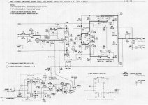
Yes, this works basically the same as the QSC.
Some random notes:
The transformer for mine was intended to have a center tap. If you choose not to use a center tap then you will need to add the artificial power supply ground and hum balance circuit from the QSC circuit (R7,8,TR2, etc.).
I actually built mine originally for a subwoofer. As such I used a pair of bias diodes similar to the QSC but no bias pot. I used a resistor in series with each diode selected to provide 0.34V across the collector load resistors for the drivers (the base of the outputs). The amp sounded great even though it was biased in AB+B. Note that the diode bias also requires a pull-up to the positive rail of the opamp and well as one on the negative rail. QSC uses about a 5V zener in series with their resistors (it's actually part of the current limiting), which I didn’t do either. My amp worked fine with only 3mA in the pull-downs, QSC uses 10mA.
For Hi-Fi I thought the traditional transistor on the heatsink would be more comfortable for most people, the method shown with the opamp only driving the top side and the pull-down to the negative supply is used in the Rockford-Fosgate amplifiers.
I didn’t like the QSC method of generating the +/-15V for the opamps, it is also part of their current limiting. I had the +/-15V available for the rest of my circuits anyway, so I used it.
Full current fold-back current limiting may be used by inserting a low ohm sense resistor in series with the negative speaker terminal (see Crown schematics if you need such). This gives a very low signal referenced to ground that is amplified by an opamp and then run into a comparator circuit.
I’ll add some more notes later when I have the time.
The cascode is the same idea as the Leach superamp. With 20 outputs per channel, a full 105CFM 4.5" fan and two feet of heatsink per channel there's enough SOA to drive a pair of lab horns 6dB into clip on peaks all night. If the plug doesn't melt off the extension cord It's failrly easily converted to class G (not H) by replacing the lower bias resistors for the slave banks with a zener and boot strapping the upper resistor to make a CCS. Then add the necessary commutation and steering diodes and the lower voltage supply. THAT's not a project for a first-timer, however.
hi there,
I've not tried cascodes yet.....but I'm going for class G when rails are above +/-100vdc or so....yet you've got a nice work there!
djk:
I've not tried such a topology before....and since i found it easy mounting the ouputs, this would be my next project.....pls. add more insights on this......
thanks
The power transformer needs to be a low-leakage type. The QSC has a screen over the primary, and another between the two secondaries.
An inexpensive split-bobbin E&I type works quite well. For inexpensive toroids I would recommend one per channel.
I would recommend building a small one for evaluation purposes to see if it is good enough for your hi-fi needs. One pair of outputs on ±40V would be easy enough to do. The basic drive circuit may be re-used with more outputs as desired.
A class G output stage, QSC style:
http://www.qsc.com/support/library/schems/Discontinued/MX Series/MX2000.pdf
Note that the cases of all the outputs are still grounded.
Also note that this current limiting scheme does not sound good.
I like the looks of this amp design djk.
Since the cases (collectors) of the outputs are grounded, that means they do not have to be insulated from the heatsink, and the heatsink can be bolted straight to the case?
Also, you say one pair of outputs (as the schematic shows) will run on +/-40vdc. How many pairs would be required for +/-60vdc operation? I'm guessing three pairs?
hi djk,
what would be the best power supply for the opamp?
would it be optimum if we will step it down from the
main rails with resistor-capacitor-zener network? or
from a seperate rectified (18-0-18)AC winding with
7815's and 7915's 😉
best regards,
 trick or treat!!!!!
what would be the best power supply for the opamp?
would it be optimum if we will step it down from the
main rails with resistor-capacitor-zener network? or
from a seperate rectified (18-0-18)AC winding with
7815's and 7915's 😉
best regards,
trick or treat!!!!!I prefer to use a seperate supply.
Using zeners from the main rails requires extra diodes and resistors from the signal output node of the amplifier to the zeners to provide the low voltage supply when approaching full output .
It's easy to add the extra low voltage windings to a toroid, many come with them.
These show up on eBay with a BIN of $70 + $10 ship (USA).
http://toroid-transformer.com/AN-8458.pdf
"How many pairs would be required for +/-60vdc operation? I'm guessing three pairs?"
Yes, I would probably use three pair to allow for low impedance loads.
"Since the cases (collectors) of the outputs are grounded, that means they do not have to be insulated from the heatsink, and the heatsink can be bolted straight to the case?"
You can, but don't think you can get away with not running a big buss wire to all the outputs and the speaker ground terminals. I used inexpensive stamped heatsinks mounted direct to the PC board with a fan.
Hi djk,
Nice amplifier design!
But aren't the values of R1 and R2 switched with each other?
It seems like they must have been accidentally switched, and that the correct values should be R1=1K and R2=22K.
Otherwise, besides the low 1K input impedance, if you have 22K and 470 pF for the input lowpass RF filter, the filter's -3 dB frequency is only about 15.4 kHz, and the amplifier's output is down by 5.5 dB at 20 kHz. But with R1=1K and R2=22K, the amplifier output's frequency response is only down by about 0.1 dB at 20 kHz and the -3dB point is at roughly 111 kHz (at least when simulated using an LT1115 opamp).
ALSO, I think that R1 should be split into two series resistors, each 1/2 R1's value, with 2x C1 (i.e. 1000pF) going to ground from between them, to isolate C1's capacitance from the negative opamp input, to prevent high-frequency oscillation tendencies.
With the original input filter topology, i.e. R1=1K and C1=470pF, there is a potential for oscillation at 8 MHz or so (which I did also observe, when simulating with 0.4v p-p square wave input with 1 us rise/fall times).
But, by splitting R1 into two 499-Ohm resistors, with C1 (1000pF) connected to ground from between them (which I think is the usual method for inserting an RF filter before an opamp's _inverting_ input), the frequency-response peak at around 8 MHz goes away (and the oscillation I saw is also gone).
Other than that, it looks great.
It's unfortunate that we have to worry about capacitive loads. Otherwise, lowering the values of C2 and C3 could significantly lower the distortion. Actually, if the total load capacitance was not more than 1000pF, it looks like maybe C2 and C3 could be lowered to about 10 pF, dividing the THD@20KHz by four. But I haven't yet included parasitics like wire and trace impedances, et al, in my simulation. So try that at your own risk.
Again, nice work!
I am looking for my schematic for you. I did a 746 watt 8 ohms a long time ago. +- 120 rails, I used two transformers from Dunlap-Clarke that they used for their 250 per channel amp.
It is doable. the caps where 20,000 uf 150v from GE and I used MJ15023 and MJ15024, I think ft of about 1 meg and 250 volts it did about 250 volts usec and I used one to drive 9 more on each rail 20 transistors per side. I was well with in the SOA.
When I first fired it up my kids would complain of its interference with the TV so it was very fast till I rolled off the feedback
I used a opto isolator to de-couple the temp sensing circuit in the output for the bias.
I only built one channel, the project was cut short by life.... if you know what I mean ....
gootee, thanks for looking at this.
Yes, the 1K and 22K are swapped. A 100ohm~330ohm resistor on the inverting input will probably be adequate, but your idea sounds fine too.
C2 and C3 were made large on purpose to allow for differences in parts for the average constructor and not having to worry about having it oscillate. If one has a stack of parts and a good scope he could reduce the values, be sure and check with all possible loads and over temperature too. I'm lazy so I overcompensate.
Hi~~
Nice looking amp, very simple, very flexible looking...
I have been searching and searching for a HV amp to run a piezo welding transducer for some experimentation ....
The transducer has a max. impedance of 30 ohms at it's resonant frequency of 28kHz...
The max. power is 200 watts... So I would need to drive it with 77V RMS or 110v pk...
The transducer body is the GND, so a bridged design is not applicable...
It's really hard to find suitable schematics, and I don't have the expertise to design one myself... So, I'm very happy I came across this thread~~
Thanks,
Michael
Hi again~~
Please excuse me for being a newb... I have loads of questions, I tried to simulate the design but it didn't go well...
Anyhow... I'll play with the simulator and see if I can get it working right....
My questions are....
1) What is (x3) on R13, is that 3x 15ohm resistors in series for a total of 45 ohms...
Or is it 3x 5ohm resistors for a total of 15ohms... ??
2) I'm assuming for my purposes (200watts) I should double the output, so 2x mj21193 and 2x mj21194...
3) Other than caps c7 and c8, is there a general voltage rating for the rest of the caps?
4) Regarding themal stability... And since q1, q2 and q5 are TO-220 package, whereas q3 and q4 are TO-3 package... Should they all be on 1 heatsink... or can I put the TO-220's on one, and the TO-3's on another?
If they have to go on the same heatsink, I could machine something, I have a CNC mill at my disposal..
Thanks, And sorry for asking so many question 🙂
Michael
Hi~
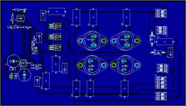
Thought I'd do layout with eagle...
Forgot the voltage regulators.. and I'm not sure about the heatsink yet...
So I will have to make numerous changes...
Some of the parts weren't in eagle so I sub'd a few things...
Well, here it is so far....
Cheers,
Michael
Thought I'd do layout with eagle...
Forgot the voltage regulators.. and I'm not sure about the heatsink yet...
So I will have to make numerous changes...
Some of the parts weren't in eagle so I sub'd a few things...
Well, here it is so far....
Cheers,
Michael
Attachments
Hi,
how do you connect the To3 output devices to the heatsink without the heatsink touching/shorting all the other soldered pins on the back of the PCB?
To247/264 would be much easier to implement, particularly if the devices are near the PCB edge.
how do you connect the To3 output devices to the heatsink without the heatsink touching/shorting all the other soldered pins on the back of the PCB?
To247/264 would be much easier to implement, particularly if the devices are near the PCB edge.
"1) What is (x3) on R13, is that 3x 15ohm resistors in series for a total of 45 ohms...
Or is it 3x 5ohm resistors for a total of 15ohms... ??"
R13 is about 5 ohms (3x15R) . It needs to be noninductive and the power rating proportional to the ±rails of the amplifier. 3x 3W may not be enough for sustained use at high frequency.
"2) I'm assuming for my purposes (200watts) I should double the output, so 2x mj21193 and 2x mj21194... "
For sustained use at high frequency the design should be de-rated, I would use at least four pair.
"3) Other than caps c7 and c8, is there a general voltage rating for the rest of the caps?"
C8 and C9 are the power supply caps, and actually represent the transformer, rectifiers, and filtercaps (with bypass caps). The center tap of the transformer is the speaker output.
C3 and C9 need to be rated at at least 250V, in your case I would use 400V.
I would probably consider some form of resonant drive, paralleling the piezo with an inductor.
"4) Regarding themal stability... And since q1, q2 and q5 are TO-220 package, whereas q3 and q4 are TO-3 package... Should they all be on 1 heatsink..."
Yes. For your use I would turn down the bias to about 340mV across R7 and R10 (optimal class B bias).
I would probably not use this design for your application.
I will try and draw up something more suitable for your use this weekend, it will be even simpler and use one IRF hex-fet for the output.
krazatchu said:Hi again~~
Please excuse me for being a newb... I have loads of questions, I tried to simulate the design but it didn't go well...
Anyhow... I'll play with the simulator and see if I can get it working right....
My questions are....
1) What is (x3) on R13, is that 3x 15ohm resistors in series for a total of 45 ohms...
Or is it 3x 5ohm resistors for a total of 15ohms... ??
2) I'm assuming for my purposes (200watts) I should double the output, so 2x mj21193 and 2x mj21194...
3) Other than caps c7 and c8, is there a general voltage rating for the rest of the caps?
4) Regarding themal stability... And since q1, q2 and q5 are TO-220 package, whereas q3 and q4 are TO-3 package... Should they all be on 1 heatsink... or can I put the TO-220's on one, and the TO-3's on another?
If they have to go on the same heatsink, I could machine something, I have a CNC mill at my disposal..
Thanks, And sorry for asking so many question 🙂
Michael
Hi Michael,
I have what I think is a working LTspice model for the amplifier. You can download all of the LTspice files needed, at:
(Right-click on the link and select "Save Target As": )
http://www.fullnet.com/~tomg/djk_amp2.zip
(If you need LTspice, I have a direct download link, here:
http://www.fullnet.com/~tomg/gooteesp.htm )
One thing I did not figure out is how to connect the power supply model. The simulation runs fine if I just use a couple of ideal voltage sources. But I also have a simple simulated center-tapped-transformer linear supply on the schematic, that causes strange things to happen if I connect it. I didn't look at it for very long. But obviously I was doing something wrong, with that.
gotee: I believe those MJ21193/MJ21194 models from Onsemi you are using are broken. I was quite perplexed of the behaviour of a circuit I simulated earlier with these. You simulation worked fine when I replaced them with something else.
megajocke said:gotee: I believe those MJ21193/MJ21194 models from Onsemi you are using are broken. I was quite perplexed of the behaviour of a circuit I simulated earlier with these. You simulation worked fine when I replaced them with something else.
Oops! Thanks! I had wanted to check to see if I had any OnSemi models, in there, but then forgot.
I wasted almost a whole day, once, because of a "problem" that was actually being caused by broken OnSemi spice models for BD139 and BD140, and which was fixed by using the models available from Fairchild. And I have seen a lot of complaints about other broken OnSemi spice models, from other spice users.
Does anyone know if there are any better models available, anywhere, for the MJ21193 and MJ21194?
- Status
- Not open for further replies.
- Home
- Amplifiers
- Solid State
- ~700w ampifier