gootee said:
Hi Michael,
I would tend to want to leave a little more headroom for the 16.9 Watt R13 dissipation. I'd probably go with a 25W minimum, and would prefer 35W or more. And (assuming it would even matter for your application,) you probably also don't want to give it a chance to have the signal modulate the resistance value due to self-heating (which is even (much) more important for the resistors involved in any feedback loops, by the way). And I wonder if a non-inductive resistor would be worth considering, there.
A Caddock MP930-series 5 Ohm 30 Watt in a TO-220 case might be nice, for $3.72 qty 1 from mouser.com for example, but would require a heatsink. Mouser also has the Ohmite TCH35P series in a 5.1-Ohm value good for 35 Watts, in a similar package, for $5.66 qty 1. They also have the Vishay/Sfernice TO-220 LTO30 (30W) and LTO50 (50W) Thick Film series, with 5.0-Ohm values of either one for $3.66 qty 1.
If it turns out that wirewound IS alright to use, then, since they're so much cheaper, I'd probably go for 75W or 100W of them, just in case the self-heating R-modulation might be a significant problem. Note that the common cement-encased wirewound types do have about a +350 ppm per deg C temperature coefficient.
I hope that someone who knows more about it will comment on whether or not the self-heating effects are even worth worrying about, in this application.
Why would the resistor value here be that critical? A driver voice coil will easily change its resistance by 50% due to thermal compression. I'm pretty sure this will have much more impact than the zobel resistor changing its value by a few percent.
megajocke said:
Why would the resistor value here be that critical? A driver voice coil will easily change its resistance by 50% due to thermal compression. I'm pretty sure this will have much more impact than the zobel resistor changing its value by a few percent.
Thanks. That's why I was asking. But also note that he is not driving a speaker.
krazatchu said:
The pb50 & 58 (an14) are almost enough... I will have to take a closer look at them... I'll also have to read up on slew rate, as I'm unclear on the meaning... There are lots of things I don't know~~
Maybe you could just run two or more of them in parallel... (which might get expensive, in their case). Keep in mind, too, that, in general, almost any amplifier that can give you enough voltage can give almost as much current as you want, if you use enough of them in parallel. Usually, all you would need to do is add a small (say 0.1 Ohm) resistance in series with each one's output, and then join all of those together. (National's AN-1192 has some example calculations for paralleled power amps, that you could probably adapt to your situation; not the amps, there, just the type of calculations.)
I only mentioned the max slew rate to indicate that they had enough speed/bandwidth. It just means that they can change their output voltages at up to 100 volts per microsecond, under the right conditions. It also gives you an idea of their bandwidth, which is hundreds of kHz, in their case.
The MP111FD is meant for driving the piezo actuators in inkjet printer heads...
OK. But they mention someone using it to drive several hundred of those in parallel. I didn't look at it closely. But, for any different application, all that would matter are the specs.
---
I also didn't check the apexmicrotech.com website, to see what other models they might have. Those just happened to be mentioned in some older appnotes that I already had on hand.
---
Maybe you could post a question in the rec.crafts.metalworking group, at http://groups.google.com . You might also want to cross-post it to sci.electronics.design . First, I'd do some searches there, since it now has the archive of all Usenet newsgroup message-traffic, since about 1981. It's a goldmine!
R13 must be non-inductive, the bulk foil TO-220 resistors will work OK.
Remember that the part rating is for 25°C and must be de-rated for the mounting resistance, size of the heatsink, and ambient temperature.
I received a 3rd degree burn from a 5W wirewound running at only 2W. Reading the data sheet revealed that at 5W the delta T would be 250°C, so with 2W the delta T would have been 100°C (plus 25°C ambient). I touched it and found out the hard way that it was 125°C!
In actual use it would be likely to have to de-rate by a 5:1 ratio, ie a 50W part should only be run at 10W.
"Why would the resistor value here be that critical? A driver voice coil will easily change its resistance by 50% due to thermal compression. I'm pretty sure this will have much more impact than the zobel resistor changing its value by a few percent."
The C9/R13 is mainly for amplifier stability with no load or a highly inductive load, for this application let's change C9 to 0.047µF 400V and R13 to 10R.
You should measure the transducer to see what the capacitance and ESR is, and use that as the model in your simulation program. I suspect you will see around 0.5µF, and that amp will need more outputs to drive a pure capacitor. Hopefully the capacitance will be lossy and have a fair resistive component.
As you say, if the amp doesn't work out for your application, it will make a nice sub amplifier.
If you like, I could send you a Crest CKV800. It's rated at 92V RMS maximum and will drive as low as 12.5 ohms, -3dB at 148Khz. Freight might be a bit at 60lbs, I only need $200 for the amplifier.
http://www.crestaudio.com/media/pdf/ckv800_11-20-96.pdf
Hi~
I changed C9 to 47nF and R13 to 10R ...
At 40kHz, power dissapation is 8.031 Watts...
At 30kHz, power dissapation is 4.752 Watts...
It's unlikely that I will go as high as 40kHz, however I will look for something in the area of 40 Watts (8.031 x5)...
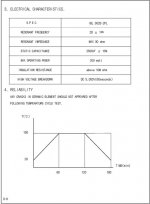
ESR would be the impedance at resonance, wouldn't it?
The data sheet says this is 30 ohms max.
The static capacitance is labeled on the transducer,
It says 2.620pF.. this must be wrong, it should be 2.620nF... the pf is part of the label and the number is written... the data sheet says 2500pf...
I will keep in mind the Crest amp, if this doesn't work out, I may take you up on that offer~~
Attached is the data sheet for the transducer...
Thanks,
Michael
I changed C9 to 47nF and R13 to 10R ...
At 40kHz, power dissapation is 8.031 Watts...
At 30kHz, power dissapation is 4.752 Watts...
It's unlikely that I will go as high as 40kHz, however I will look for something in the area of 40 Watts (8.031 x5)...
ESR would be the impedance at resonance, wouldn't it?
The data sheet says this is 30 ohms max.
The static capacitance is labeled on the transducer,
It says 2.620pF.. this must be wrong, it should be 2.620nF... the pf is part of the label and the number is written... the data sheet says 2500pf...
I will keep in mind the Crest amp, if this doesn't work out, I may take you up on that offer~~
Attached is the data sheet for the transducer...
Thanks,
Michael
Attachments
Interesting ....
I just simulated with a 30 ohm load in parallel with a 2.62nF cap...
There is a bit of distortion on the downward cycle of the sinewave but it clears up after about 2 ms....
When I lower R13 to 5ohms, the distortion is less and it clears up in less than 1 ms...
I'm not sure this is the proper way to model the transducer, I have some notes on how to model the transducer, I will have to find them and check it...
Michael
Got a question....
Do I need such large caps c7 and c8? could they be smaller?
Hence cheaper...
Thanks,
Michael
Do I need such large caps c7 and c8? could they be smaller?
Hence cheaper...
Thanks,
Michael
Diss-regard my last question.... If it ends up doing audio duty, then i'll already have the caps....
Ysterday I went to the local electronics market and got the parts... everything except the transformer...
Total cost so far, I'm not sure, I always buy extra ... Sometmes 2x, sometimes 5x extra.... but I spent about 100$US...
Anyhow, I'll have to figure out what to do about the transformer,
I could only find atoroid with 220 on the primary and +/-110 on the secondary... I need around 140 ac before rectifier...
You need to measure the transducer on a bridge and find out how much C and series R it looks like.
Hello..
I have no idea what that means!! Google doesn't exactly help, too many other possiblilites for bridge~~
From your previous post , I'm assuming I should measure the ESR... after reading up on ESR meters, it looks like a handy tool to have...
Somewhere (again, not sure of the source) I read that, at ressonance, when the phase angle between current and voltage is zero, the reactance cancels out and all that is left is just the resistance... which would be 30 ohms...
From what I understood, since I will be only running at ressonance, I shouldn't have to consider that capacitance...
Is this correct?
Thanks!!
Michael
On another note...
I haven't yet looked at the phase angle, I didnt have a second probe for my scope and channel b wouldn't switch to 5 volts...
Since then, I have got another probe and used some pot cleaner on the scope, channel b's voltage control is ok now....
What I did do previously was, using one of the 100W amps, drive the transducer at about 27 watts ... When I approached 28,250 Hz, the transducer started to slide (with little friction) around on the desk... 50Hz up or down and the effect disappeared...
Thanks!
If you still want to google for bridges, you could use quotes and look for things like "capacitance bridge", "wheatstone bridge", "impedance bridge", et al.
Or, look for messages at diyaudio.com by Conrad Hoffman. He seems to be the most-enthusiastic local bridge-master. I've seen some posts of his, relatively recently, about quick-n-dirty benchtop bridge-building. I suggest you consider emailing him, if you're still interested in it. He could probably also tell you whether or not you need to worry about it. (Or, now that I've put his name, here, maybe he'll comment in this thread.)
Or, look for messages at diyaudio.com by Conrad Hoffman. He seems to be the most-enthusiastic local bridge-master. I've seen some posts of his, relatively recently, about quick-n-dirty benchtop bridge-building. I suggest you consider emailing him, if you're still interested in it. He could probably also tell you whether or not you need to worry about it. (Or, now that I've put his name, here, maybe he'll comment in this thread.)
Speaker Workshop can measure impedance. Most modern sound cards are 96k, so you can measure to 48 kHz. And then go fit an equivalent circuit model, if you are so inclined.
Hi~~
I have been on mandatory vacation this week....
Lunar New Years in Korea is a long holiday~~
Anyhow, prior to vaction I went hunting for parts...
Everything I found at the local electronics market, with the exception of the transformer....
The highest output voltage I could find was 110v... with a 220 primary, we use 220 in Korea...
To get 125VDC, I will need about 140VAC...
So I was thinking, is it possible to use two transformers, the primaries in parallel and the secondary in series?
Thanks,
Michael
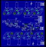
I did a little work on the layout...
All the transistors are on the copper side...
I'll use two heatsinks, suspended by bolts and use a nut for a spacer to keep the heatsink off the copper...
The to-220 and to-126 transistors will fit between the heatsinks, and will be bolted to one side...
I didn't have a footprint in the eagle library for the output resistor, but I left enough space using two resistors to make it fit...
Can anyone see any problems with this layout?
Tomorrow I'll check the ESR since the transducer is at my office...
Thanks,
Michael
Attachments
I am left wondering, if you need to ask this question should you be left with assembling an amplifier with +-125Vdc inside it?krazatchu said:To get 125VDC, I will need about 140VAC...
So I was thinking, is it possible to use two transformers, the primaries in parallel and the secondary in series?
you may not like the tone in my message, but I am thinking about your continued membership of this Forum.
If my babelfish worked correctly, I can distill the following... you want two transformers in series (at least the output side)...
Yes, no problem as long as they are the same.
If you connect input (primary) side in series , you would need twice the supply to get the original speced outputs....
So, the same as your tv, fridge and lights, loads on the mains side goes in parallel...
I trust this was only a communication issue, because Andrew is makeing valid points, this is realy lethal territory.
- Status
- Not open for further replies.
- Home
- Amplifiers
- Solid State
- ~700w ampifier