Progress report...
Built the mains light bulb tester... checked the transformer wiring... everything ok there..
Getting 50VAC on each side of the toroid... Output from FWBR is 125 VDC... so 62.5 up and 62.5 down with respect to gnd....
Built the pcb, assembled everything... powered up with Mains bulb tester... light came on dim for half a second then did not glow or had a faint glow....
Checked the output with nothing on input... had 136VAC out... not good...
Checked the power going to the opamp... high side is 15vdc... low side was -1.6vdc...
Checked the 18VAC transformer, its ok...
Pulled the opamp and checked the low side, pin4... same... 1.6vdc
Checked the wiring diagram vs datasheet on LM79L15.. ok
Checked the polarity on the caps.. ok
So... it could be the fwbr (low volt one, not the high volt one), or the regulator, or either one of the caps(electrolyte or tantalum)....
My guess is the regulator... will have to pull the heatsinks off to get at the solder side since I didn't leave much leg room on the regulator... maybe i can just crush the T0-92 case and solder another on top...
Prolly do that tomorrow....
Those 136VAC must be a measurment error - some DMMs just half wave rectify, average and correct by a factor. It's probably DC on the output as the opamp is missing a supply.
Do check that you have 100VAC between the extreme ends of the secondary windings. If they are in phase (0V AC between the FWBR AC terminals) it will kind of work but you will have much worse transformer and filter cap utilization under load.
The 18V transformer, is it 18-0-18? If it is just a single 18V you have to half wave rectify to get symmetrical supplies - which should be fine BTW.
ah... yes, I will check the dc component.. I was going to scope it but then I found the problem with the -15vdc supply...
Already checked the toroid, yes there is 100 VAC across the two secondarys, with the other wires tied to center...
The smaller transformer is 18-0-18 ... to a fwbr, then cap, then regualtor, then another cap...
Unfortunately, I mounted the fwbr and regulator nearly flush to the board... just maybe I can get a reading off the center pin (in)of the regulator... that should tell me if its the fwbr or the regulator...
The copper side is covered by the heatsink...
Thanks!!
Ok, managed to check the dc voltage at pin 2 of the regulator, the input pin...
Its about -19 VDC... The output, pin 3 is about -1.63 VDC .. .
So the regulator is toast... Since I don't feel like taking the heatsink off... I think I will crush it and solder another on top...
Thanks!!
Its about -19 VDC... The output, pin 3 is about -1.63 VDC .. .
So the regulator is toast... Since I don't feel like taking the heatsink off... I think I will crush it and solder another on top...
Thanks!!
My suggestion: Replace with 7815 and 7915 instead of the TO-92 parts so you don't have to worry about the current foldback - a problem when using dual supply opamp circuits. It might not be a faulty regulator actually - a replacement would probably do the same.
I had some trouble when using the TO-92 versions to power a small opamp circuit, sometimes one of the rails wouldn't come up. Current draw was ~25mA but this was too much!
Replacing with TO-220 parts solved the problem.
edit:
How can it be that you are getting 19V DC from a 18-0-18 transformer? I'd expect at least 24V with light load. Is the positive voltage the same? The center tap is connected to the ground connected to the collectors of the output transistors isn't it?
hi~
Ya, I thought 19vdc was a bit low as well... I can't get a probe on the high side since I mounted the components to close to the board...
Oops my r16 isn't 4.7k ohm... I've got a 4.7 ohm on there...
That should be it~~
thanks!!
Ya, I thought 19vdc was a bit low as well... I can't get a probe on the high side since I mounted the components to close to the board...
Oops my r16 isn't 4.7k ohm... I've got a 4.7 ohm on there...
That should be it~~
thanks!!
Well, after I changed r16 to the proper 4.7k,
Now I'm getting -15.2vdc low and 15.0vdc high...
Before the regulator it's now -22.3vdc..
So everythings ok there...
I double checked the voltage across the the secondarys, where they connect to the FWBR, its 93 VAC..
Across the +/- of the FWBR its 127 VDC...
So everything looks good there too ...
Hmm.. Output is still giving me 63 VDC / 140 VAC ...
After I turn off the power, the voltage stays for about 8 seconds and drops rapidly to 0....
I'll put the scope on it and see what it is...
Thanks!!
Michael
hmm..
I put the scope on the output.. its dc...
I checked the values on the other resistors.. they're ok...
I checked the output of the opamp.. . nothing...
I fed the opamp a 1 Vpk sine ... nothing on pin 1 (ouput)..
I checked to make sure the signal was getting to pin 2, ok...
I tried another lm833n ... same same...
Pin 3 (feedback) is seeing about 1.2volts...
So... the omp amp isn't op'ing and I'm also getting dc out...
Strange... I will take another look at my layout and see where I went wrong...
Thanks!!
Michael
Simulation shows...
68 VDC is what you get when the opamp is giving 0 V out...
So.. Either I have 2 bad opamps...
Or the "mains bulb tester" isn't letting enuf current thru...
Or the (L series) regulators aren't giving enuf current ...
I don't know...
I will test the opamps on the breadboard...
Perhaps I will check to see how much current is coming out of the regulator...
Any suggestions.. ???
Thanks!!
I think you need to post a detailed schematic of your entire circuit, including the entire power supply, on the same schematic if possible.
Opamps are ok... configured as voltage follower on breadboard with +/-12vdc...
Input equal to output...
I checked the datasheet on the LM79L15... output of 100 mA ...
Datasheet on the LM833n says... supply current is typ 5mA, max 8mA ...
hmm...
Input equal to output...
I checked the datasheet on the LM79L15... output of 100 mA ...
Datasheet on the LM833n says... supply current is typ 5mA, max 8mA ...
hmm...
I tried to measure the current into the opamp...
I bent up pin4 (-15vdc) and put the DMM in series...
Got 0.00 mA ... nothing at all...
Hmm....
I bent up pin4 (-15vdc) and put the DMM in series...
Got 0.00 mA ... nothing at all...
Hmm....
Megajocke... I will try the T0-220 regulators...
I don't have any 15's, only 12's and 5's .... And I have to get to my other job soon...
I will pick some up tomorrrow and give it a try...
Thanks!!
edit: Simulation only shows 3.14 mA DC on the -15 VDC line...
I don't have any 15's, only 12's and 5's .... And I have to get to my other job soon...
I will pick some up tomorrrow and give it a try...
Thanks!!
edit: Simulation only shows 3.14 mA DC on the -15 VDC line...
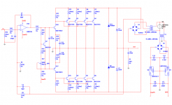
krazatchu said:Here is the whole schematic...
Only thing missing is power switch, power light, fans and fuses...
Sorry it's a little squished...
If you really have only a 330 nF (film?) cap from the regulator outputs to ground, that is a problem. The datasheet says that a larger cap (with higher ESR) is required there, for stability. (Maybe one of them 'oscillated to death'. 🙂
The output cap should also be as close to the regulator pins as possible, or soldered directly to the pins.
They suggest a minimum 25 uF aluminum electrolytic (or, 10 uF in another part of the datasheet), OR, a minimum 1 uF if using solid tantalum.
Note, too, that if you use around 100 uF or more on the output, you would then want to add a high-current protection diode across the input and output pins.
I would probably keep the regulator output caps fairly small (e.g. 33 uF to 47 uF aluminum electrolytics), to try to make sure that the opamp gets powered-up before its inputs become active.
Also, as someone else suggested, the TO-220 versions of the regulators would probably be much more reliable.
And, I'm not sure, offhand, if this applies to fixed-voltage regulators. But, with adjustable regulators, you would always want to run the conductor for whatever is connected to the regulator's reference pin (ADJ pin, but GND pin for the fixed regs) to the load SEPARATELY from the main ground for that dual supply, so that the opamp's return currents, which cause dynamic voltage drops across the ground trace's parasitic impedance, wouldn't create a 'bouncing' reference point for the regulator.
If you did use adjustable regulators, you could also bypass the adjust pins' resistors and get much quieter power supply rails.
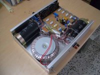
P.S. If that is a bypass cap lead showing, near the opamp, in your photo (difficult to tell), you definitely need to fully insert it, so that the leads are as short as possible.
The 330nF caps are polarized tantalum... I had them from an AVR project I did before...
The label says u33, so I'm asusming they are 0.33uF..
I put them as close the the opamp as possible, as that is suggested for microcntrollers...
I guess this rule doesn't apply with analog....
The regs are fixed.. .they are lm79L15 and lm78L15...
I will up the cap values and change the regs to T0-220...
I didn't consider using any special grounding topologies ...
Since I'm just using it for ultrasonic, I'm not too concerned about THD...
edit: you can see one of the caps (yellow, tantalum) by pin8, there is another by pin4 but it's behind the +/-18VAC wires (black and yellow)...
I tried to keep the leads short but I used the wrong footprint, the tantalum caps were an after thought....
Thanks!
Michael
follow the decoupling recommendations in the manufacturer's datasheet. If it needs tweaking after that then make what seem appropriate adjustments.krazatchu said:The 330nF caps are polarized tantalum........I put them as close the the opamp as possible..........I tried to keep the leads short
Similarly add decoupling to the input of the regs. Again most manufacturers tell the users this.
There already is a pair of 4700uF caps on the inputs of the regulators...
I will read the datsheet for specifics...
Thanks,
Michael
I will read the datsheet for specifics...
Thanks,
Michael
Interesting...
The regs I have are national... So I just checked the datasheet...
LM79L15 T0-92
Under typical applications, fixed output regulator 100mA ...
The output caps are 0.1uF... so the tantalums I have should be ok then...
For the TO-220 package, it recommends 1uF tantric, or 25uF electro...
I will swap the regs to To-220 and change the caps...
An extra cap on the input isn't nesscary according to he datasheet since its less than 3" away...
Thanks!!
- Status
- Not open for further replies.
- Home
- Amplifiers
- Solid State
- ~700w ampifier