Woot~ What alot of info to process! Thanks for all the replies!!
Allrighty, in reverse order...
On the OnSemi website they have 4 choices, they are all identical... and dated 2003...
Here are some old ones from '98...
Oh... will have to do 1 per post...
Allrighty, in reverse order...
Does anyone know if there are any better models available, anywhere, for the MJ21193 and MJ21194?
On the OnSemi website they have 4 choices, they are all identical... and dated 2003...
Here are some old ones from '98...
Oh... will have to do 1 per post...
Attachments
And to continue in reverse order...
Gootee thanks, I tried to download it but the link timed out.. I'll try it again later... or from home...
DJK, thanks so much, answered all my questions and then some~~
Somewhere I read something about driving piezo's...
I'm pretty sure it was from a website but it might have been in a pdf...
Anyhow, it said the two halves of the AB amp should overlap.... having both top and bottom on for some time....
As I recall, the explanation given was to recover some of the power as the piezo is reactive....
I'll see if I can find that again...
A little info on my prior progress of this project...
A while ago I purchased a kit amp, 2x 100 watts, based on the 2sc5200 & 2sa1943... My recently aquired used O'scope tells me I'm getting 40 Vpk which translates into less than 30 watts while driving the 30 ohm transducer...
I was considering inverting one amp and bridging them.. that would give me about 165 watts... however, I would lose the gnd and then the transducer body would be hot... not so good...
I have built an AVR based DDS and also an XR2206 based function gen... I was thinking about using PLL to implement resonant tracking, the phase angle between the voltage and current in resonance is near zero....
perhaps I might even try to implement a simple generator/pll on an AVR... but I haven't even begun to even research that yet ....
I've also built an AVR based frequency counter...
If anyone wants links to any of these projects, just ask...
All of the AVR based stuff I found on web, including the source code... I haven't programed in years...
DJK, if you could come up wih something without too much effort, that would be great!!
I did a little searching on IOR's website... they have some very capable Hexfet's...
Wish I knew what do with them 🙁 !! I know a little bit of everything but not much of anything specific....
Thanks!
Michael
Is the piezo bender a bi-morph or a uni-polar?
If uni-polar it should be able to be driven with a single ended signal swinging between ground and up to -220V (modulated). A parallel resonant inductor would buffer the signal and make the load look (more) resistive to the amplifier.
If uni-polar it should be able to be driven with a single ended signal swinging between ground and up to -220V (modulated). A parallel resonant inductor would buffer the signal and make the load look (more) resistive to the amplifier.
Hi~
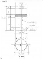
It's a BLT (Bolted Langevin Transducer).... Pzt material is c-203...
It should be driven bi-polar as unipolar may over stress the pzt...
Attached is jpg, material is alu 2024-t6 (aircraft grade)...
There are two pzt donuts (shown by cross hatch), between them is a thin piece of metal for connecting the ac power...
The gnd connects to another thin piece of metal above the donuts or anywhere on the body...
The two halves are bolted and the bolt is insulted from the donuts by a teflon insert...
About the inductor..
The transducer's resonant frequency will be affected by mechanical loading, which will be dynamic...
I think this may be a problem with the inductor, since it should match the resonant frequency...
Perhaps, the variation in resonance might be too small to make a differnce... this I don't yet.. some experimenting may be in order...
Anyhow, for the dynamic nature, I was leaning towards a PLL drive or perhaps I could use feedback to let it self oscillate...
Thanks,
Michael
Attachments
krazatchu said:A little info on my prior progress of this project...
A while ago I purchased a kit amp, 2x 100 watts, based on the 2sc5200 & 2sa1943... My recently aquired used O'scope tells me I'm getting 40 Vpk which translates into less than 30 watts while driving the 30 ohm transducer...
I was considering inverting one amp and bridging them.. that would give me about 165 watts... however, I would lose the gnd and then the transducer body would be hot... not so good...
You're on the right track here, but there may be an easier way - it's called a transformer. If the load is always high compared to audio frequency, then you could use a trafo to match impedances and make better use out of your amplifier. You can also hook 'ground' anywhere you want to if it's galvanically isolated. If for example you want the extra operating safety margin, you could start off bridged then go throuh the trafo. A 70 or 100 volt constant-voltage transformer run backwards may be the ticket. Effects of leakage inductance can be canceled out with the proper cap.
Consider class D using the transducer as part of output filter capacitance. You may even consider self oscillating class D.
Wg_ski, I had previously considered using a transformer, and after doing some research, I came to the conclusion it wasn't practical... Also, I was having some difficulty locating a suitable one...
Since the operating frequency is rather high compared to AC mains (28,000 Hz vs 60 Hz)...
A transformer suitable for this application would have to have a powdered iron core... I believe the skin effect comes into play here as well...
If I'm wrong, please correct me, I certainly would prefer the easiest route~~
Eva, Class D would be more effecient, however I hardly have a basic understanding of Class AB...
Unless some one has a working schematic of a high voltage Class D.... that isn't too difficult to assemble with toner transfer etc...
Thanks,
Michael
At 28Khz a ferrite transformer would work fine. Any power ferrite material would do. Also, skin effect losses at 28Khz are not a problem, at least not with magnet wire having 1mm diameter or less. Turn counts for that application won't be high, say 20 to 60 (it depends a lot on core size and voltage requirements).
One pair of 5200 and 1943 should be good for 100W, but into 4ohms
Measuring over higher impendances is not realy a measure of power but only an indication that the amp provided what was requested from it...
Lets say it has 35V rails, and you drive a 4R load...That is a peak of about 6A and an RMS average about 4A
i.e. well over 100W but going above 100W you will likely see distorion climbing greatly.
Do the same sums with a 30R load.
The amount of current required is roughly the voltage of the output signal divided by the load resistance... so as the load goes higher impendance, less and less power is required... no indication of power available though.
Following the same math, the 30R load will require less than 1 A to reach the full voltage available from the output rails. Which matches your results closely.
The solution, for high ohm, low efficiency speakers... a nice high voltage amp.
"One pair of 5200 and 1943 should be good for 100W, but into 4ohms"
At 28Khz?
Driving a capacitor?
BANG !
At 28Khz?
Driving a capacitor?
BANG !
For sure you are right, I merely understood the gentleman was complaining about getting only 30W out of his 100W amp but testing over a 30R load...
Allrighty~~
Well, I got the amp to simulate, everything seems allright at +/-125 Vdc...
I measured the power dissapation in r13 to be 16.9 Watts..
I figure 4x 5watts at 20 ohms in parallel should be sufficient...
Power disapation in the rest of the resistors is rather low, according to the sim...
I re-drew the board in eagle, made it a littel tighter and smaller...
Thanks,
Michael
Is something I would like to avoid!!BANG !
Well, I got the amp to simulate, everything seems allright at +/-125 Vdc...
I measured the power dissapation in r13 to be 16.9 Watts..
I figure 4x 5watts at 20 ohms in parallel should be sufficient...
Power disapation in the rest of the resistors is rather low, according to the sim...
I re-drew the board in eagle, made it a littel tighter and smaller...
Thanks,
Michael
Hi~~
Are caps c7 and c8 polarized?
On the schematic, it's not indicated, but on the qsc schematic, it
shows they are...
Are any of the other caps polarized?
Thanks,
Michael
Are caps c7 and c8 polarized?
On the schematic, it's not indicated, but on the qsc schematic, it
shows they are...
Are any of the other caps polarized?
Thanks,
Michael
krazatchu said:Allrighty~~
Is something I would like to avoid!!
Well, I got the amp to simulate, everything seems allright at +/-125 Vdc...
I measured the power dissapation in r13 to be 16.9 Watts..
I figure 4x 5watts at 20 ohms in parallel should be sufficient...
Power disapation in the rest of the resistors is rather low, according to the sim...
I re-drew the board in eagle, made it a littel tighter and smaller...
Thanks,
Michael
Hi Michael,
I would tend to want to leave a little more headroom for the 16.9 Watt R13 dissipation. I'd probably go with a 25W minimum, and would prefer 35W or more. And (assuming it would even matter for your application,) you probably also don't want to give it a chance to have the signal modulate the resistance value due to self-heating (which is even (much) more important for the resistors involved in any feedback loops, by the way). And I wonder if a non-inductive resistor would be worth considering, there.
A Caddock MP930-series 5 Ohm 30 Watt in a TO-220 case might be nice, for $3.72 qty 1 from mouser.com for example, but would require a heatsink. Mouser also has the Ohmite TCH35P series in a 5.1-Ohm value good for 35 Watts, in a similar package, for $5.66 qty 1. They also have the Vishay/Sfernice TO-220 LTO30 (30W) and LTO50 (50W) Thick Film series, with 5.0-Ohm values of either one for $3.66 qty 1.
If it turns out that wirewound IS alright to use, then, since they're so much cheaper, I'd probably go for 75W or 100W of them, just in case the self-heating R-modulation might be a significant problem. Note that the common cement-encased wirewound types do have about a +350 ppm per deg C temperature coefficient.
I hope that someone who knows more about it will comment on whether or not the self-heating effects are even worth worrying about, in this application.
In post #37, DJK said it should be non-inductive...
I didn't know the cement/ceramic ones were wire wound...
Michael
I didn't know the cement/ceramic ones were wire wound...
Michael
I noticed that Supertex.com has some documents with information about piezo drivers. Their AN-D16 has a very-simple-looking schematic for a high-voltage high-gain amplifier, and also one for a high-voltage ramp generator with a note to refer to AN-D12 for details. Both schematics note that their applications include piezo drivers.
Hey~
I have come across quite a few schematics for high voltage amps while searching for an applicable driver...
All of them I have found, with the exception of a really old class ab amp, were low current... Applicable to bi-morphs and perhaps positioning systems...
Previously I did a considerable amount of googling.. maybe about 3 or 4 weeks off and on...
The AN-D12 pdf says max. peak power is 3 watts 🙁 ...
I think I will give DJK's amp a try... If it doesn't go well, I could always use it for my pc.... I'm currently using a Cambridge SoundWorks 2.1 ... It's about 5 or 6 years old, plastic is turning yellow...
With DJK's amp running a sub and the 2x 100 watt (2sc5200, 2sa1943) kit amps running satelites... would make for a nice pc sound system...
Thanks~~
Michael
Have you seen Figure 9 and Figure 10, in AN-272, at national.com? Figure 10 claims up to 1000v at 300 Watts. And figure 9 will put out basically whatever the power amp inside the feedback loop can give (a McIntosh 75 in the figure).
OK, it looks like the Fig 10 circuit is only unipolar, and has slow fall-times. Too bad.
At any rate, it seems like some of the other high-voltage booster circuits, there, could be easily adapted to give more output current. Linear.com has a similar appnote, AN18.
And what about http://www.apexmicrotech.com ? They appear to have some high-power, high-voltage opamp-like 'power boosters'. In their AN-14u appnote, for example, they mention their model PB50 as being capable of 200 volts at 2 amps, and PB58 that can do 300 volts at 1.5 Amps. Both apparently can slew at 100 volts/us.
Apex's AN-44u appnote looks like it has some good basic information about piezoelectric stuff, in general, and also has an example of a piezo-actuator driver, although that one looks like 5 Watts or so.
Oh wait, they do also talk about their MP111FD power opamp, for driving a piezo transducer array. They say that the MP111FD is a 100-volt device (+/-100v, apparently) with a 500 kHz power bandwidth and a 50-Amp pulse capability.
Hmm...
Figure 10 (AN-272) is quite interesting... the lm3524 thats driving either side is some kind of pwm....
The pb50 & 58 (an14) are almost enough... I will have to take a closer look at them... I'll also have to read up on slew rate, as I'm unclear on the meaning... There are lots of things I don't know~~
The MP111FD is meant for driving the piezo actuators in inkjet printer heads...
Thanks,
Michael
- Status
- Not open for further replies.
- Home
- Amplifiers
- Solid State
- ~700w ampifier