A 6AS7/6080 is at the other end of the scale with regard to power on that Octal pinout. Depending on the power supply you should expect 10-15 Watts of audio. With a 400V PS & using 2X 6080, mine made a very clean 30W. The major challenge will be the driver circuit, of which there are many alternatives. This amp was built as a 'proof of concept'. A different kind of driver. Think I've put this one on DIY before, some may have seen it.🙂
Attachments
With a 400V PS & using 2X 6080, mine made a very clean 30W. The major challenge will be the driver circuit, of which there are many alternatives. This amp was built as a 'proof of concept'. A different kind of driver.
If I were to go for a 6AS7 at higher voltage, I would probably go for a 12AT7 or 6N2P front end, and 350-375 volt supply. Should be able to swing pretty well at the voltages needed. My preference is to lower voltage/higher current (like shoog, my favorite op point for these is 100 volts/100mA, -30-33 volts G1) but it does limit you to 7~8 watts or so. Nice and linear at these ranges though, and simpler to drive.
60mA, 160 volts, -60 volts G1 is a pretty good operating point too. Easy enough off of a 220 volt supply. Maybe go garter bias off of ~280 volts? 1200~1600 plate-to-plate load is about right, and reasonably easy to come across. A 50VA, 115:115x18 volt toroid (two series connected 9 volt windings, or parallel 18 volt windings) will give ~1300R, and would give good performance at an affordable price. Figure ~11-12 watts or so? It's been awhile 🙂
The noval input PCB is geared towards such advanced chicanery, and should prove useful for different loadouts 😉
Last edited:
I enjoyed talking with you at Burning Amp yesterday. Thinking about your design, I remembered that I have a number of 12GN7 pentodes and thought they might work reasonably well as outputs. Wouldn't need a high-gain first stage. Any thoughts?
thanks,
Skip
thanks,
Skip
I don't have any experience with them personally, so would have to do some reading on them, but it's a pretty versatile setup, so might could work well.
6SL7 6SN7 PP Amp
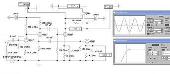
Curiosity drove me to analyze this circuit with a PP 6SN7 as the output. For sure the available audio would be limited, so what were the other challenges? I was very familiar with the basic layout. Over the years I’d built many amps like this, but none with ordinary low power triodes.
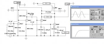
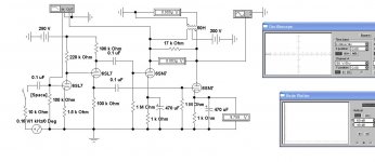
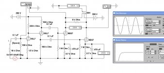
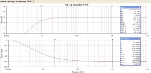
First principles tell us that for triodes the load impedance reflected by the Output Transformer (OPT) should be at least 2X the plate resistance of the tubes used. The nominal rp of the 6SN7 at a 250V supply is 7.7K. So in a PP hookup we have 15.4 K. Looks like the OPT needs to reflect at least 30K in order to keep distortion to a reasonable level.
In order to detect a signal level condition where D% would begin to be objectionable, I measured the no signal cathode voltage of the RHS 6SN7 cathode. If it lifts off the no signal condition then distortion is a sure thing.
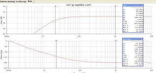
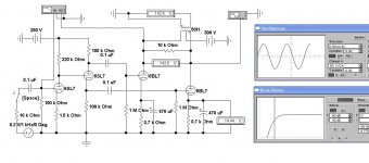
With the 17K load the power output looks like ~0.93 Watt. But distortion has appeared in the waveform.
Going to a 34K load the power drops to 0.78 Watt, but the distortion is gone.
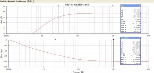
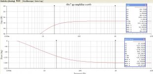
The other problem is finding a small, low power OPT with enough primary inductance. For the simulations I’ve assumed the inductance to be 50H. That kind of part would be difficult to find. The low frequency rolloff in this circuit is determined primarily by the OPT inductance. As tested the LF rolloff is down 3db in the mid 20s Hz.
If the OPT inductance were something like 20H, then the LF rolloff would be in the 50s Hz, 3db down.
Some negative feedback would help. But it is important the amp be as clean as possible before NFB is applied.🙂
Curiosity drove me to analyze this circuit with a PP 6SN7 as the output. For sure the available audio would be limited, so what were the other challenges? I was very familiar with the basic layout. Over the years I’d built many amps like this, but none with ordinary low power triodes.
First principles tell us that for triodes the load impedance reflected by the Output Transformer (OPT) should be at least 2X the plate resistance of the tubes used. The nominal rp of the 6SN7 at a 250V supply is 7.7K. So in a PP hookup we have 15.4 K. Looks like the OPT needs to reflect at least 30K in order to keep distortion to a reasonable level.
In order to detect a signal level condition where D% would begin to be objectionable, I measured the no signal cathode voltage of the RHS 6SN7 cathode. If it lifts off the no signal condition then distortion is a sure thing.
With the 17K load the power output looks like ~0.93 Watt. But distortion has appeared in the waveform.
Going to a 34K load the power drops to 0.78 Watt, but the distortion is gone.
The other problem is finding a small, low power OPT with enough primary inductance. For the simulations I’ve assumed the inductance to be 50H. That kind of part would be difficult to find. The low frequency rolloff in this circuit is determined primarily by the OPT inductance. As tested the LF rolloff is down 3db in the mid 20s Hz.
If the OPT inductance were something like 20H, then the LF rolloff would be in the 50s Hz, 3db down.
Some negative feedback would help. But it is important the amp be as clean as possible before NFB is applied.🙂
Attachments
-
 6SL7 6SN7 PP Amp A 34K Load Schema w Results 2nd Pass.JPG84.3 KB · Views: 444
 -
 6SL7 6SN7 PP Amp A 34K Load Freq & Phase 2nd Pass.JPG93.4 KB · Views: 429
 -
 6SL7 6SN7 PP Amp A 17K Load Schema w Results 2nd Pass.JPG83.4 KB · Views: 427
 -
 6SL7 6SN7 PP Amp A 17K Load Freq & Phase 2nd Pass.JPG92.7 KB · Views: 406
 -
 6SL7 6SN7 PP Amp A 17K Load No Load 470 Cathode Caps.JPG74.8 KB · Views: 420
I've toyed the idea of running 16 ohm speakers off of them to get the distortion down even more, but an easy solution is to add another pair of tubes 🙂
One could also split the difference to something like ~22k or so. A 10k or so transformer for an EL84/6V6 application may be a good start with some creative impedance (mis)matching.
If looking at good speakers to pair with them, look at design using the Faital pro 3FE25-16, a pair in a .04x scale Karlsonator would be a very good match, and can be built for ~$50 USD.
More Ideas & Simulations Using 6BL7 or 6BX7
PP Amps Using 6BL7 or 6BX7
Both have the same pinout as the 6SN7 so could be plugged right into the pcb Ling is designing. But they need 1.5A for the heater rather than 0.6A.
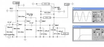
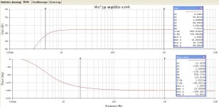
Running the simulations for all three alternatives shewed the plate dissipation was always exceeded while running on a B+ of 300V. The final simulation is run at 250V B+. The final sim is run using a 12H OPT which the Hammond 125E claims to be. It is a universal type, so many taps allow trial of different loads.
From the sims it appears we could expect 2-3 Watts using the 6BL7 in PP at 250-300V. The 6BX7 looks OK for 5-6 Watts. All might be less, depending on the efficiency of the OPT.
The low plate resistance of the 6BX7 should drive Ling’s power frequency transformers OK for those who would prefer to try that. None of the OPT’s proposed are what we could call ‘HIFI’, so NFB up to 10 db is probably safe. Beyond that there could be problems, especially with the power freq OPT, no telling what it will do. Need to hook it up & try!🙂
PP Amps Using 6BL7 or 6BX7
Both have the same pinout as the 6SN7 so could be plugged right into the pcb Ling is designing. But they need 1.5A for the heater rather than 0.6A.
Running the simulations for all three alternatives shewed the plate dissipation was always exceeded while running on a B+ of 300V. The final simulation is run at 250V B+. The final sim is run using a 12H OPT which the Hammond 125E claims to be. It is a universal type, so many taps allow trial of different loads.
From the sims it appears we could expect 2-3 Watts using the 6BL7 in PP at 250-300V. The 6BX7 looks OK for 5-6 Watts. All might be less, depending on the efficiency of the OPT.
The low plate resistance of the 6BX7 should drive Ling’s power frequency transformers OK for those who would prefer to try that. None of the OPT’s proposed are what we could call ‘HIFI’, so NFB up to 10 db is probably safe. Beyond that there could be problems, especially with the power freq OPT, no telling what it will do. Need to hook it up & try!🙂
Attachments
-
 6SL7 6BX7 PP Amp 6.6K Load Freq Phase H125E OPT 250V PS.JPG93.9 KB · Views: 97
 -
 6SL7 6BX7 PP Amp 6.6K Load Schema H125E OPT 250V PS.JPG79.8 KB · Views: 111
 -
 6SL7 6BX7 PP Amp 8K Load Freq & Phase.JPG93.2 KB · Views: 101
 -
 6SL7 6BX7 PP Amp 8K Load Schema.JPG82.5 KB · Views: 105
 -
 6SL7 6BL7 PP Amp 10K Load Freq & Phase.JPG92.8 KB · Views: 113
 -
 6SL7 6BL7 PP Amp 10K Load Schema.JPG78.3 KB · Views: 150
Another way to connect a pair of double triode tubes
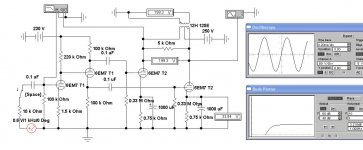
This connexion uses a pair of 6EM7s, a double triode but they are dissimilar. The advantage is the power dissipated in the PP pair is spread over two tubes, not all in one place as the other ccts discussed earlier. In this case the power triode part also has a lower mu of 5.4 & rp of 0.75 K, so can drive the output to greater power.
The other triode in the envelope is hi-mu (64) & acts as the driver section of the amplifier. Otherwise the amplifier schema looks the same as the earlier ccts. Unfortunately, this will not work with Ling’s PCB. This kind of topology was used in quite a few amplifiers but the tubes used were triode-pentodes such as the ECL82. The resulting amps were in the 5 Watt class.
With the Hammond 125E the LF rolloff looks like ~13 Hz, should make everyone happy. This cct does need somewhat more B+ current, it is no longer a flea project. Depending on the OPT used, something like 6-8 Watts should result.
Using the earlier referenced power freq transformer for the OPT looks OK. NFB with care.
In 1999 I did build a SET amp using the 6EM7. It managed 3W with 8% distortion, mostly 2H. That is about what we could expect from a 2A3. With 19 db of NFB that was reduced to 0.8%. 3H was 0.3% & 4H was 0.1%. Nothing significant at higher order. The distortion was measured using a Pico Technology virtual instrument.
The original article was published in Glass Audio magazine, Vol 12, Number 4, 2000.🙂
Attachments

This connexion uses a pair of 6EM7s, a double triode but they are dissimilar. The advantage is the power dissipated in the PP pair is spread over two tubes, not all in one place as the other ccts discussed earlier. In this case the power triode part also has a lower mu of 5.4 & rp of 0.75 K, so can drive the output to greater power.
The other triode in the envelope is hi-mu (64) & acts as the driver section of the amplifier. Otherwise the amplifier schema looks the same as the earlier ccts. Unfortunately, this will not work with Ling’s PCB. This kind of topology was used in quite a few amplifiers but the tubes used were triode-pentodes such as the ECL82. The resulting amps were in the 5 Watt class.
With the Hammond 125E the LF rolloff looks like ~13 Hz, should make everyone happy. This cct does need somewhat more B+ current, it is no longer a flea project. Depending on the OPT used, something like 6-8 Watts should result.
Using the earlier referenced power freq transformer for the OPT looks OK. NFB with care.
In 1999 I did build a SET amp using the 6EM7. It managed 3W with 8% distortion, mostly 2H. That is about what we could expect from a 2A3. With 19 db of NFB that was reduced to 0.8%. 3H was 0.3% & 4H was 0.1%. Nothing significant at higher order. The distortion was measured using a Pico Technology virtual instrument.
The original article was published in Glass Audio magazine, Vol 12, Number 4, 2000.🙂
I've used both the 6BM8 (ECL82) and 6/13EM7 tubes and love them both. I have a partially built PP version of a 13EM7 amp which seems to have a ton of promise. I appreciate the schematic for your PP version. But I do wonder if we're getting a little far afield given that the original idea was PP using garter bias and unusual (normally preamp) tubes as outputs, along with cheap toroidal transformers as OPTs (and in my case interstage). I don't want it to stop but I wonder if it deserves it's own thread?
I think it's fine to keep here, since it's all along the same lines as the original, just scaled up a bit. Speaking of which, I've played with an even smaller version, with the subminiature Russian 6N16B. Maybe .4W or so? What to call it? The mite? The chigger? 🙂
Last edited:
Another Alternative for the Flea Version
Another alternative twin triode that looks interesting for the flea version would be the 12BH7. Plate resistance is somewhat less than the 6SN7 & would better drive the power freq OPT.
Need to keep in mind appearance, so looks like a 12AX7 for the driver circuit. The 12BH7 dissipation is a bit limited. But since rp is lower than the 6SN7, power output would be in the same ball park. Might make a nice bookshelf amp.
Some folks might question how I could compare a plain Jane power triode in
the 6EM7 to the 2A3. Specs given in the tube manuals are obtained under lab conditions, regulated power supplies & measured at the tube, not thru anything like an output transformer. Nor is there a driver amp, the signal used comes from a very low distortion oscillator & perhaps a narrow band filter. With many of the earlier tubes, distortionless meant ‘did not exceed 5%’.
Once these tubes were into a real amplifier, distortion depends a lot on the rest of the circuit. So don’t be surprised when the resulting amp does not measure like the tube manual sez!! It also depends very much on the designer.🙂
Attachments
Garter Bias Test
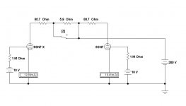
This test is based on the PP 6SN7 circuit of the flea power amplifier.
For the regular 6SN7 the model used is straight out of the RCA Receiving Tube Manual. So the plate is at 250V while grid bias is -8 volts. The resulting plate current would be 9 mA.
The other tube called 6SN7 X for the test, the plate & grid are taken to be the same as the ordinary tube, but the resulting plate current is 11 mA, a 22% difference.
The bias circuit is all at DC. The output transformer for DC appears only as its primary resistance.
The OPT needs to be included in the test (Garter A1). For the Hammond 125E, one side of the primary is 80.7R while the other is 86.6R. Key 'Z' allows adjusting the difference. The One K cathode resistors hold the plate currents within 0.021%. For the rest of the tests, the difference in the two halves of the OPT primary can be safely ignored.
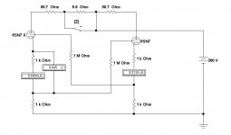
A 2nd test (Garter A2) with the 6SN7 X connected shews a current difference of 4.6%. In order to shew how effective the bias resisters are, a comparison is made in Garter C. Here bias batteries are used, no cathode NFB. The difference is 21.9%, similar to the 6SN7 vs the 6SN7X.
For the 3rd circuit including the garter, refer to Garter B. The difference has been reduced to 1.8%.🙂
This test is based on the PP 6SN7 circuit of the flea power amplifier.
For the regular 6SN7 the model used is straight out of the RCA Receiving Tube Manual. So the plate is at 250V while grid bias is -8 volts. The resulting plate current would be 9 mA.
The other tube called 6SN7 X for the test, the plate & grid are taken to be the same as the ordinary tube, but the resulting plate current is 11 mA, a 22% difference.
The bias circuit is all at DC. The output transformer for DC appears only as its primary resistance.
The OPT needs to be included in the test (Garter A1). For the Hammond 125E, one side of the primary is 80.7R while the other is 86.6R. Key 'Z' allows adjusting the difference. The One K cathode resistors hold the plate currents within 0.021%. For the rest of the tests, the difference in the two halves of the OPT primary can be safely ignored.
A 2nd test (Garter A2) with the 6SN7 X connected shews a current difference of 4.6%. In order to shew how effective the bias resisters are, a comparison is made in Garter C. Here bias batteries are used, no cathode NFB. The difference is 21.9%, similar to the 6SN7 vs the 6SN7X.
For the 3rd circuit including the garter, refer to Garter B. The difference has been reduced to 1.8%.🙂
Attachments

I'm confused. First, where are you seeing a 22% difference in currents of the two halves of the PP pair (or are you saying something else)? And I'm not sure I understand the direct connection of cathode to ground in the left tubes in the first two images (and the similar connection to the garter in the 3rd). Like I said, I'm confused.
I see garter bias in the 3rd image (ignoring the bypass connection on the left tube) but nowhere else. So I really can't make any sense out of what you're doing.
Can you clarify what you've done and what you think you're seeing?
I see garter bias in the 3rd image (ignoring the bypass connection on the left tube) but nowhere else. So I really can't make any sense out of what you're doing.
Can you clarify what you've done and what you think you're seeing?
I'm confused.
Back again, I thought someone would jump in here with an explanation while I was away from this thread. It looked like the explanation was very clear, I guess not.
First, where are you seeing a 22% difference in currents of the two halves of the PP pair (or are you saying something else)?
When using simulations, each component needs to be defined as fully as possible. So for this test I defined one of the 6SN7 triodes (labeled 6SN7) as drawing 9 mA, while the other (labeled 6SN7 X) I purposely set to pull 11 mA under the same conditions. That was in lines 2 & 3 in the previous post.
So 11 /9 represents the 22% I mentioned.
I see garter bias in the 3rd image (ignoring the bypass connection on the left tube) but nowhere else. So I really can't make any sense out of what you're doing
Garter bias is the 3rd image, but there is no bypass, no capacitors. All caps & transformers are left out, they have no effect in a DC circuit. Not sure where the bypass you are referring too is.
And I'm not sure I understand the direct connection of cathode to ground in the left tubes in the first two images (and the similar connection to the garter in the 3rd).
All the cathodes in 2 & 3 are connected to ground thru 1K resistors far as I can see. Show me.
Like I said, I'm confused.
Yes
Can you clarify what you've done and what you think you're seeing?
And I do know what I’m seeing, I’ve built something like 50 amps over my lifetime. You will find some of them in back issues of Glass Audio & AudioXpress magazines. But never my day job.
Garter Bias circuit was in this thread from the very beginning, it looked like a good place to compare Blumlein’s garter bias to both normal cathode bias & fixed bias. I’d never seen the garter cct before, so I was curious.
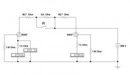
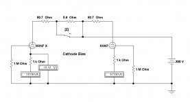
So fixed bias in this example causes the tube currents to differ by 21.9%, very much like we should expect. And cathode bias helps a lot, the difference is reduced to 4.59%. There is a cct attached for that.
The Blumlein connexion reduces the difference to 1.82%.
The Garter looked like it might be used to advantage in a more common amplifier. So I’ve done one for KT66s as used in the original Williamson. To be posted soon.
One great advantage of simulations is there is no smoke when an error is made!🙂
Back again, I thought someone would jump in here with an explanation while I was away from this thread. It looked like the explanation was very clear, I guess not.
First, where are you seeing a 22% difference in currents of the two halves of the PP pair (or are you saying something else)?
When using simulations, each component needs to be defined as fully as possible. So for this test I defined one of the 6SN7 triodes (labeled 6SN7) as drawing 9 mA, while the other (labeled 6SN7 X) I purposely set to pull 11 mA under the same conditions. That was in lines 2 & 3 in the previous post.
So 11 /9 represents the 22% I mentioned.
I see garter bias in the 3rd image (ignoring the bypass connection on the left tube) but nowhere else. So I really can't make any sense out of what you're doing
Garter bias is the 3rd image, but there is no bypass, no capacitors. All caps & transformers are left out, they have no effect in a DC circuit. Not sure where the bypass you are referring too is.
And I'm not sure I understand the direct connection of cathode to ground in the left tubes in the first two images (and the similar connection to the garter in the 3rd).
All the cathodes in 2 & 3 are connected to ground thru 1K resistors far as I can see. Show me.
Like I said, I'm confused.
Yes
Can you clarify what you've done and what you think you're seeing?
And I do know what I’m seeing, I’ve built something like 50 amps over my lifetime. You will find some of them in back issues of Glass Audio & AudioXpress magazines. But never my day job.
Garter Bias circuit was in this thread from the very beginning, it looked like a good place to compare Blumlein’s garter bias to both normal cathode bias & fixed bias. I’d never seen the garter cct before, so I was curious.
So fixed bias in this example causes the tube currents to differ by 21.9%, very much like we should expect. And cathode bias helps a lot, the difference is reduced to 4.59%. There is a cct attached for that.
The Blumlein connexion reduces the difference to 1.82%.
The Garter looked like it might be used to advantage in a more common amplifier. So I’ve done one for KT66s as used in the original Williamson. To be posted soon.
One great advantage of simulations is there is no smoke when an error is made!🙂
Attachments
^ Nice clarification. I got what you meant just fine.
Garter is a neat simple way to go. It's just a couple extra cheap parts per channel, and provides great return for time/effort.
I'm also using garter with the pentode connected EL86/6CW5's that I run in my bigger amplifier. With a regulated screen voltage and toroidal outputs the balance is fantastic! Might try it on some 6V6's at some point too.
Garter bias is the 3rd image, but there is no bypass, no capacitors. All caps & transformers are left out, they have no effect in a DC circuit. Not sure where the bypass you are referring too is.<snip>
First off, I apologize if you felt I was being critical. I wasn't trying to be, just very confused. Some labelling of the images might have helped. Again, not saying there's anything wrong, just not clear to me.
But...I understand more now and appreciate your clarification. I get that you designed the two to be 22% different in current draw. I was looking for those current numbers on the first or second image but not seeing them. I see now you've included a new image with cathode bias that includes those numbers and clarifies things. That's what I thought the second image was supposed to be but wasn't (and explains why there wasn't a 6SN7x in that image, which, again, confused me since I was expecting it!).
Now I see that your first two images were just illustrating the fix for the OPTs, and there was no image for the cathode bias.
Finally, I see a connection between the left tube cathode and ground in the first two images and a connection between the left tube cathode and the junction between the cathode resistors in the 3rd image (bypassing the upper resistor). Those may not have been actual connections in the circuit but it made everything all the more confusing. And that same connection is in the last image (cathode bias) you posted in your clarifying comments. Or perhaps I'm still not understanding?
In any case, this makes more sense to me and is closer to what I would have expected. Thanks!
Carl
So, I finally managed to find a lazy enough morning to lash everything up and test the octal board. It took a little bit of fooling around with the power supply board, and after that smoke test, I went ahead and set up the board with 8R dummy resistance, and did the "smoke" test-

After checking all the important places to ensure that the voltages are coming up correctly, I hooked up some speakers and ran some tunes through it for a couple hours-

It sounds great! All voltages came up exactly as expected, and idle power draw is almost exactly 40mA total for the complete amplifier. Components chosen are pretty much the same as those in the original build, with just different value grid resistance (470K) and a different ratio for the step network at the concertina (1M/680K, instead of 1M/1M) for a tad lower voltage at the grid, which gives a smidge more voltage across the tube, for theoretically better linearity, also because I was running out of 1M resistors 🙂
I can honestly say that the board is very easy to use, and went very smooth! Once it's all soldered and stuffed, the terminal blocks make finishing the connections between everything a breeze. I can safely say that the octal board is a success! Once I get a noval board stuffed without issues during testing, I'll go ahead and start sending out a few samples for those that will be testing them.
Also, anybody have a set of 6BX7 or 6BL7 they'd be willing to send my way to test a build? If you've got a pair to offer up, I'll send you a board to play with!
After checking all the important places to ensure that the voltages are coming up correctly, I hooked up some speakers and ran some tunes through it for a couple hours-
It sounds great! All voltages came up exactly as expected, and idle power draw is almost exactly 40mA total for the complete amplifier. Components chosen are pretty much the same as those in the original build, with just different value grid resistance (470K) and a different ratio for the step network at the concertina (1M/680K, instead of 1M/1M) for a tad lower voltage at the grid, which gives a smidge more voltage across the tube, for theoretically better linearity, also because I was running out of 1M resistors 🙂
I can honestly say that the board is very easy to use, and went very smooth! Once it's all soldered and stuffed, the terminal blocks make finishing the connections between everything a breeze. I can safely say that the octal board is a success! Once I get a noval board stuffed without issues during testing, I'll go ahead and start sending out a few samples for those that will be testing them.
Also, anybody have a set of 6BX7 or 6BL7 they'd be willing to send my way to test a build? If you've got a pair to offer up, I'll send you a board to play with!
Last edited:
I have a few 6BX7/BL7 I can offer, but won't be available until later in October. I'm in the Berkeley hills.
I chatted with you briefly at Burning Amp. Great design!
-Kent
I chatted with you briefly at Burning Amp. Great design!
-Kent
No rush my man, I move slowly anyway lol.
Started mocking up a chassis, same size (10x8x2.5) Bud industries AC-1418 as I used on the first one, looks like it will all fit nicely.

Just not sure if I want to put a noval or octal version in this one. I suppose I can cut the holes for the octals, and run either really, so it isn't to critical. I can just round over the edges a bit so it looks pretty
That reminds me, I need to buy more 6N2P to play with 😎
Started mocking up a chassis, same size (10x8x2.5) Bud industries AC-1418 as I used on the first one, looks like it will all fit nicely.
Just not sure if I want to put a noval or octal version in this one. I suppose I can cut the holes for the octals, and run either really, so it isn't to critical. I can just round over the edges a bit so it looks pretty
That reminds me, I need to buy more 6N2P to play with 😎
- Home
- Amplifiers
- Tubes / Valves
- 6SN7 push pull flea amplifier project