I usually use LM317 or TL783. Wouldn't those work in an LTP?
Yes, they work, and they certainly are easy to install.
Walt Jung's AudioXpress articles describe the use of constant current sources/sinks. Part 1 describes the basics of operation:
http://waltjung.org/PDFs/Sources_101_P1.pdf
Part 2 compares LM317 constant current source/sink with a DN2540 based constant current source/sink, complete with measurements, etc.
http://waltjung.org/PDFs/Sources_101_P2.pdf
The LM317 CCS is okay, within its limits. It gets inductive as frequency goes up; its impedance goes down above 10kHz. That means an LTP with an LM317 (TL783) in its tail will have balance that gets worse above 10kHz, introducing harmonic distortion on higher frequencies. Perhaps bypassing it with a film cap helps?
The single DN2540 CCS works well and has more constant impedance with frequency.
Later updates in AudioXpress compared the cascode DN2540-LM317 against the cascode made with two DN2540s. The version with the two DN2540s performs better. That's the preferred high voltage CCS these days.
--
Yes, and I've used them (DN2540) in the tail of an LTP front end. But the output stage baffles me...
Yes, they work, and they certainly are easy to install.
Walt Jung's AudioXpress articles describe the use of constant current sources/sinks. Part 1 describes the basics of operation:
http://waltjung.org/PDFs/Sources_101_P1.pdf
Part 2 compares LM317 constant current source/sink with a DN2540 based constant current source/sink, complete with measurements, etc.
http://waltjung.org/PDFs/Sources_101_P2.pdf
The LM317 CCS is okay, within its limits. It gets inductive as frequency goes up; its impedance goes down above 10kHz. That means an LTP with an LM317 (TL783) in its tail will have balance that gets worse above 10kHz, introducing harmonic distortion on higher frequencies. Perhaps bypassing it with a film cap helps?
The single DN2540 CCS works well and has more constant impedance with frequency.
Later updates in AudioXpress compared the cascode DN2540-LM317 against the cascode made with two DN2540s. The version with the two DN2540s performs better. That's the preferred high voltage CCS these days.
--
Great info. I remember reading these articles when I was younger 🙂 If only they made a DN2540 with a built in Vref like LM317 so you didn't need basically a trimpot to adjust current.
Sorry guys, I've been super swamped and busy, and life has been relentless in keeping me from getting to my hobbies 🙂
I just stopped in to add a possible axial lead coupling capacitor option, since I've begun using this thread as a sort of ongoing blog of sorts...
The Vishay 75-MKT1813410405 at $1.40USD each looks like a neat option in a modern production part, for those that would prefer an axial to a radial/box cap-
MKT1813410405 Vishay / Roederstein | Mouser
Everybody waiting on a board, well, just sit tight 😱 My only day off is friday, and I was out of town last friday, and swamped all the others.
Also of note, I've requested the day off for Burning Amp 2018 in San Francisco, and will be taking the prototype and a few boards with me, as well as some basic info and a schematic for those interested. If anyone else will be attending and has a set of speakers that sound suitable to pair with it, just let me know 🙂
Last edited:
The MKP is better IMHO: MKP1839410404 Vishay BC Components | Capacitors | DigiKey
Looks good, mouser has them too. Still cheap!
Yes, but Digi-key isn't owned by a holdings company and they ship heavy transformers for free. Mouser wanted $45 for shipping because they exceeded a weight limit 🙂
The 6SN7 makes a very nice sounding output tube. If your speakers have high sensitivity you don't need a lot of power to get reasonable loudness. Seems like you could do better than one watt. I've got a design I breadboarded that does one watt wide band, two watts midband running both halves of a 6SN7 in parallel single ended Class A. I would expect push-pull to put out a bit more power. Probably be a few months before I build a finished version, I'll take some meaningful measurements then and post.
Higher voltage and current I've gotten just around 2 watts out of a single bottle in push-pull, and they do indeed sound very nice at these levels with sensitive speakers. Running mine conservatively works great with my current speakers, so I didn't see a point in pushing the envelope too far. I've toyed with the idea of a parallel-output version with fixed bias and source followers at the output grids, it would be easily scalable, and should provide plenty of headroom. I figure 5 watts out of a pair should be easy without unnecessarily limiting tube life in such a setup...
The current config is pretty conservative and will do 1.3 watts continuous.
I currently run the original amplifier in the garage on a pair of Karlsonator speakers using Vifa TC9FD drivers, and I don't find them lacking for average listening levels at all. My current main-use amplifier is an EL86 push-pull with the same front end of this amp, and has a very similar sound, just with much more power for louder listening/gaming/party levels 🙂 I may pull the original back inside (or build up one of the test boards) and put it back in circulation for a while, since the current speakers (karlsonator with two FaitalPro 3FE25 per box) are plenty sensitive enough to reach uncomfortable volumes without audible distortion on everything other than super bass heavy material.
My schedule changed this week, so instead of being off fridays I now will be off tuesday/wednesday, so I should have time to do some more soon.
Pick up this thread after an absence, think I'll build one with the noval inputs, 12AT7 likely. I too like them and the Tung-Sol Russian reissues are quite decent. Anyway had to share this screen grab with you of what came up when I clicked on Garter circuit link. I could say that my wife was using my lap top but that would be a fib. Don't you just love cookies?
Attachments
Lingwendil: I'm building one! But a couple of questions.
Started with your thread months ago then summer happened. Came back to it recently in the context of building it as a headphone amp for low imp. 'phones. I'll include speaker binding posts too.
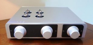
I'm going to build one using turret boards so component changes can be made easily. A chassis like the one in the attached line stage picture will be used.
Questions:
I'll definitely want to build the P.S. with the FET noise filter. Can you share the latest P. S. schematic please?
I'm leaning towards 12AT7 input tubes. What values for resistors 2, 4, 7 & 8 would you recommend? Metal-working is more my forte rather than math.
Would you recommend the Antek AS-05T280 over the 240 for higher B+?
At one point you mentioned the possibility of using 6CG7s for output duty. Does their lower dissipation compared to a 6SN7 GTA/GTB not concern you? Personally I like 6CG7s. The new Electro-Harmonix 6CG7s are decent IMHO.
Have you seen Morgan Jones's, Valve Amplifiers book, pages 298 to 309? The design of a push pull amp with concertina phase splitter and all the math involved is described and an example using a 6DJ8 and 6BQ5s is shown.
Thanks for sharing your labour of love with us.
Regards, Steve
Started with your thread months ago then summer happened. Came back to it recently in the context of building it as a headphone amp for low imp. 'phones. I'll include speaker binding posts too.
I'm going to build one using turret boards so component changes can be made easily. A chassis like the one in the attached line stage picture will be used.
Questions:
I'll definitely want to build the P.S. with the FET noise filter. Can you share the latest P. S. schematic please?
I'm leaning towards 12AT7 input tubes. What values for resistors 2, 4, 7 & 8 would you recommend? Metal-working is more my forte rather than math.
Would you recommend the Antek AS-05T280 over the 240 for higher B+?
At one point you mentioned the possibility of using 6CG7s for output duty. Does their lower dissipation compared to a 6SN7 GTA/GTB not concern you? Personally I like 6CG7s. The new Electro-Harmonix 6CG7s are decent IMHO.
Have you seen Morgan Jones's, Valve Amplifiers book, pages 298 to 309? The design of a push pull amp with concertina phase splitter and all the math involved is described and an example using a 6DJ8 and 6BQ5s is shown.
Thanks for sharing your labour of love with us.
Regards, Steve
Attachments
I'm coming in kinda late here. But saw the simple cct at the beginning using a PP 6SN7 as the power amp. Some may want to try the 6BL7, a 6SN7 on steroids in that socket. Gain & Ebb are the same, doubles power output.🙂
I'd love to try a set if I can ever score some cheap enough 🙂
Also everybody, I'm not dead, just super busy. Car trouble plus work schedule has me pretty much all booked for time. I'v got an amplifier and PSU board all populated and ready, just need to put a chassis together for it to test. Kids running around preclude the use of a clip lead testing rig anymore.
Also everybody, I'm not dead, just super busy. Car trouble plus work schedule has me pretty much all booked for time. I'v got an amplifier and PSU board all populated and ready, just need to put a chassis together for it to test. Kids running around preclude the use of a clip lead testing rig anymore.
I've got a PCM2704 DAC and a Google Nexus Phone with Neutron audio player that I'm setting up, so I should have a reasonable little system to show it off. Just need to make up a playlist of test tracks.
Should be fun 🙂
Should be fun 🙂
Not all 6BL7s are created equal. I don't know if it affects performance or not but later models of the 6BL7 only had one grid with cooling fins. It also has less gain. The being said, I did pick up a few to play with.

Looks good Ling. Still trying to carve out time to breadboard a 6AS7 version. Let me know how the PCBs are coming along.
I've got an octal one fully populated and ready to go, and a half-stuffed noval one to finish. I just want to do a smoke/function test before I send any out! I just need to find an evening to do so, and I would like to have a decent chassis to bolt it all down to as a finished amplifier too, so I don't have to have a big mess to disassemble after testing. I'm thinking of just drilling some holes in an ATX computer PSU case and going with one of them for the first prototype, It'll likely all fit just fine, and already has an IEC power entry on it to save time...
For everyone patiently waiting on PCBs I'm sorry it's taking so long. Life is keeping me pretty busy. Taking yesterday off for burning amp was the first time I've had more than one day off per week in probably three months!
For everyone patiently waiting on PCBs I'm sorry it's taking so long. Life is keeping me pretty busy. Taking yesterday off for burning amp was the first time I've had more than one day off per week in probably three months!
- Home
- Amplifiers
- Tubes / Valves
- 6SN7 push pull flea amplifier project