I'm convinced that garter bias (and cathode bias) sounds pretty darn close to the same as fixed bias, assuming a large enough bypass capacitor is use on each stack. It is naturally a bit higher distortion than fixed bias (any bypassed cathode resistor is an imperfect thing, regardless of how fancy you go) but audibly its pretty much impossible to tell the difference between them. Maybe when you get up to higher edge-of-clipping signal, but how often do we listen up in that region in hi-fi?
Garter bias is a great set-it-and-forget it, cheap and cheerful way to build, however, fixed bias is more of an engineer's-adjust-it-to-perfection type of way to go. Both get fantastic results, are nearly as complex as eachother to implement (read: not very) and each can assure perfect balance at DC, but I give the slight edge in bang-for-the-buck/effort to garter bias. If swapping about between tube types, or using really negative bias tubes, fixed bias would be a better tinkerer's solution. I think beyond about 35-40 volts garter bias gets a bit too wasteful in practice.
Garter bias is a great set-it-and-forget it, cheap and cheerful way to build, however, fixed bias is more of an engineer's-adjust-it-to-perfection type of way to go. Both get fantastic results, are nearly as complex as eachother to implement (read: not very) and each can assure perfect balance at DC, but I give the slight edge in bang-for-the-buck/effort to garter bias. If swapping about between tube types, or using really negative bias tubes, fixed bias would be a better tinkerer's solution. I think beyond about 35-40 volts garter bias gets a bit too wasteful in practice.
Last edited:
I'm trying to think through effect of fixed bias on the 6AS7 tube type, something I've never done before. It may be the current issues between tube sections aren't a big issue with fixed bias. Hmmmm. Gotta spend some time thinking this through.
In any case, not sure I fully understand it but that's an interesting bias arrangement you have there kodabmx! Is it pretty quiet?
Ah, just saw Ling's post. And I agree with the wasteful nature of the garter. I'd prefer not to burn that power if I don't need to. But I love to concept behind the garter. Guess I have more reasons for future experimentation!
Last edited:
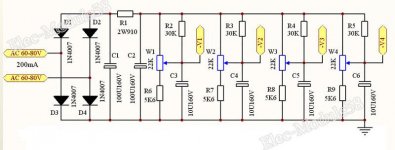
The 6AS7/6N13S garter bias arrangement I've mentioned previously (100mA,100v,-33bias) is about the furthest I would go in running garter bias, and this particular set of numbers just happens to use bog-standard common values for parts and voltage, so it's very easy to implement. Grab a sack of 10W, 330R wirewound resistors, a 120VAC transformer, a handful of 100V+ electrolytic capacitors for bypass and a couple 330k-1M or so grid resistors, PSU diodes/caps, and build it. Easy peasy and cost effective. Trivial to add a HV driver stage to. Possibly my favorite tube and operating point if running open loop, good for playing comfy music and smooching on your woman, too 🙂
Silent. And you can power it with DC if you like as the diodes will flip it the correct direction. I've even used an boost converter with great results.In any case, not sure I fully understand it but that's an interesting bias arrangement you have there kodabmx! Is it pretty quiet?
Then there is my other preferred cathode biasing: CCS bypassed with a large cap. It's basically a programmable resistor... LM317 for up to about 30V, TL783 for up to about 100V (I like to leave a safety margin on the max voltage of ICs).
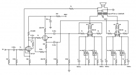
Here's an example of what I did with the 6N13S (6AS7G, 6080) before I changed to the above fixed biasing circuit.
Attachments
Yes, I ultimately plan to try the "CCS" bias approach too, and compare it with the garter. I hadn't looked into higher voltage regulators like the TLs yet but I know they are out there. I want to approximate the same operating points for a reasonable comparison. But I just love the simplicity of the garter and the minds that came up with it in the absence of transistors! I suppose I could even try a tube CCS...
My understanding is a tube CCS is wasteful and doesn't work as well. That said, I use active tube loads in place of load resistors in some of my circuits. Similar to John Broskie's Aikido, but without the Aikido noise cancelling.
Indeed, garter works extremely well for it's initial cost and simplicity. Sometimes it can actually be even more useful such as in the case you have too much B+. You could waste it in a dropping resistor, or use it to lower distortion and get better DC balance.
Indeed, garter works extremely well for it's initial cost and simplicity. Sometimes it can actually be even more useful such as in the case you have too much B+. You could waste it in a dropping resistor, or use it to lower distortion and get better DC balance.
Last edited:
A tube CCS requires a high voltage negative rail, and a pentode ideally...
I've used an EL86 as a tail CCS for a EL84 triode connected differential amplifier output before, it worked well but was a bit complicated. If you wanted to, you could go for an EL86 CCS per cathode, and tie the cathodes together with back-to-back caps, or a single big non-polar, but that's approaching the realm of totally unnecessary overkill and decadence 🙂
I've used an EL86 as a tail CCS for a EL84 triode connected differential amplifier output before, it worked well but was a bit complicated. If you wanted to, you could go for an EL86 CCS per cathode, and tie the cathodes together with back-to-back caps, or a single big non-polar, but that's approaching the realm of totally unnecessary overkill and decadence 🙂
A tube CCS requires a high voltage negative rail, and a pentode ideally...
Is that true? I've used a CCS in the tail of a 12AT7 (LTP) that used a negative voltage (much like what you mention), and I frankly want to avoid that complication. But my thinking was to use a low voltage tube in the cathode circuit (maybe a battery tube like 3S4 that has a workable low plate voltage), something that doesn't need a negative supply for a 6AS7 with anywhere from 30-50v or more grid bias... Obviously I have a lot to figure out about tube ccs...
Last edited:
Well, after a lot of research, I'm thinking a tube CCS in the tail for 6AS7s may not be in the cards. Obviously the 3S4, as with many battery tubes, won't handle the 100mA current, and that current isn't easy to come by in general. I see a bunch of issues related to this approach. I had briefly pondered a 6AS7 as the CCS but can't figure out how to configure it as a CCS in this case. I haven't abandoned it, but...
No updates yet. I've been super swamped with work, at a new location with a longer commute home, so I haven't had any time to mess with things. Money has been a little tight so I've been waiting a bit before I order more parts to populate the noval board, and a couple PSU boards. I'm currently out of most of the caps needed, so I've got to make an order soon. If I can make it to the post office tomorrow I'll try to get some boards sent out to the testing crew, but it depends on if I work or not, and family obligations. All I've managed to do so far is a partial population of the noval board, a partial PSU, and a complete populated octal board. Still trying to decide what loadout of tubes I want to run on the noval board, I'm leaning towards the 6N2P just so I can use pretty much the same components that I have on the octal builds for comparison. I'm considering a 6AS7 build using the 6N2P or 12AT7 up front, but I need to order transformers if I go that route, and I'm not in a spot to do that yet financially, especially since I've got a 6V6 design I also want to build, so I need to figure out what I want more I suppose.
Hopefully a more meaningful update Soon™ 🙂
Hopefully a more meaningful update Soon™ 🙂
Well, after a lot of research, I'm thinking a tube CCS in the tail for 6AS7s may not be in the cards. Obviously the 3S4, as with many battery tubes, won't handle the 100mA current, and that current isn't easy to come by in general. I see a bunch of issues related to this approach. I had briefly pondered a 6AS7 as the CCS but can't figure out how to configure it as a CCS in this case. I haven't abandoned it, but...
An EL34 could run as a CCS tail for the 6AS7.
Thanx. I'll look at it. I would have thought the voltage across the tube would put the cathodes pretty high on the 6AS7, but there's so much for me to learn about tube CCS.
6AS7 was designed to be a pass tube for voltage regulators, with its cathodes at B+ voltage. Its cathodes can be lifted way above its heater voltage and it will still be okay. Max DC heater to cathode voltage is 300V.
300V is enough for a cathode-biased EL34 to work in as a CCS.
A 6AS7 wouldn't make a very good CCS. You want it to have high gain, so it appears as a large impedance in the tail. That's why everybody uses DN2540 depletion mode MOSFETs. You get high gain and end up with high impedance for little volts burned off.
Last edited:
Hmmmm. I suppose that's right about the 6AS7 cathode, Rongon. I hadn't thought of that.
Re: impedance in the tail as a pass tube, I'm not sure what you mean. In general I think of PS needing to be low impedance, at least from the point of view of the signal circuit. Could you explain more. Or maybe since that's a bit off-topic can you think of any threads or links that might help me understand?
Re: impedance in the tail as a pass tube, I'm not sure what you mean. In general I think of PS needing to be low impedance, at least from the point of view of the signal circuit. Could you explain more. Or maybe since that's a bit off-topic can you think of any threads or links that might help me understand?
Here's an explanation of tube differential amplifiers:
Vacuum Tubes Part 4 Differential: A more elegant solution. Article By Grey Rollins
Part 4 describes the diff-amp without a constant current sink (CCS) in the tail.
Part 5 describes the CCS itself.
A quick 'n dirty answer to your question is that a constant current sink (CCS) presents a very high impedance to the joined cathodes of the LTP (like putting a really high value of resistor there). This applies current feedback to the triodes, equalizing their gain. If both triodes of the LTP have the exact same plate load resistance, then the constant-current, high impedance load on the cathodes will enforce balance (i.e., each triode will amplify its half of the signal equally).
You can make a high impedance load by using a relatively high value of resistance, perhaps 22k ohms. But if each half of the LTP draws 8mA, for a total of 16mA drawn through the tail, that's 22,000*0.016 = 352V (!!!). That resistor will get hot, too. It'll be dissipating 5.63W, so you'll need to use a 15W part that's rated for at least 400VDC (not easy to find) and you'll need something like a 750VDC power supply.
Using a depletion mode MOSFET, it's possible to make a CCS (current limiter) that will enforce that 16mA current in the tail while using only perhaps 50V from its drain to its source. The MOSFET's gain is very high, so it makes a 'stiff' current limiter, giving you the equivalent of perhaps 100k ohms (or higher) impedance. That's 5X higher impedance (stiffer current limiting) using 7X less voltage from your power supply. That is much more achievable.
When the gain from the two halves of the LTP is exactly balanced, even order harmonic distortions are cancelled out from the push-pull output signal. If you use a tube like 6SN7 that makes very little odd order harmonic distortion, you'll end up with a very low distortion push-pull output.
___________________________
When there's a low impedance load in the LTP's cathodes (as in a small value of resistance of perhaps 560 ohms), there is little if any current feedback being applied to the cathodes of the LTP. Now the tubes are free to amplify as much or as little as they 'want' to. Since every device is a little different, chances are that the two halves of the LTP are not going to be perfectly matched at all frequencies, so one will amplify more than the other, varying with frequency -- even if both halves of the LTP are fitted with exactly equal plate loads.
If the gain of the two halves is not balanced, even order harmonic distortions don't cancel (as much), and there is higher distortion in the push-pull output signal.
That's an overly simplified explanation, due to my rather rudimentary understanding of these things. But I hope it helps some.
--
The flea-power push-pull 6SN7 amp uses this push-pull action to achieve low distortion within its power output limits.
__
As for why a 6AS7 wouldn't make a good tail CCS, the reason is that it's a low-mu triode. (Very low mu, in fact.) That means it doesn't amplify that much, so it wouldn't amplify the cathode impedance by much to the LTP's tail.
You could use a pentode as a CCS. An EL86 would work pretty well.
But a depletion mode MOSFET like DN2540 or 10M45S works better, because they have a lot of gain, so they can amplify the impedance a lot, while they also require less voltage across themselves (drain to source).
Basically, you want the 'resistor' in the LTP's tail to 'look' like a really high value (like 100k ohms or higher). But you don't want to waste all the voltage and heat an actual 100k resistor would have to burn off in the LTP tail. So you use an active current regulator instead.
Now if you ask me the mechanism by which a current regulator creates that high impedance, I wouldn't be able to explain. Maybe someone else can help with that.
--
I've never done an LTP, but I've used CCS for the cathodes before. I usually use LM317 or TL783. Wouldn't those work in an LTP?
They'll work, but a discrete CCS would work better. Bypassed they work well, but if running as a true LTP/Differential a higher impedance CCS is nicer to interact with things less.
- Home
- Amplifiers
- Tubes / Valves
- 6SN7 push pull flea amplifier project