I hope to finish the amp tomorrow.
I have an advice for you. When you will start the amp for the first time makes these steps.
1 make a start delay for the 6c33c anode voltage, recommended at least min 2min
2 start the amplifier with the lowest anode voltage you have for 6c33c and highest bias voltage to keep the tube for at least 6 hours with the lowest anode current.
This is a small burn in for 6c33c, I broke two tubes because I start the tube at 210v with 220mA current
3 With the C3 in place the amplifier will oscillate so take it out
4 Use a 3.9k resistor instead of R2 1k on input stage
The output transformers are to small in my opinion I wonder how they sound. The choke are bigger the OPT?
For the input stage I will use four types of tubes
1 6H8C
2 6H9C
3 6SN7 GT made by GE nos tune
4 6SN7 GTB made by Raython
For driver
1 6C2C
2 6J5 made by RCA black tube
What kind of tubes you will use?
Good luck
Last edited:
Thanks for the advise Gabriel.
For what reason, as mentioned in your point 4, you change the value of this resistor?
I use 6sn7GT and 6j5gt
Regards.
José
For what reason, as mentioned in your point 4, you change the value of this resistor?
I use 6sn7GT and 6j5gt
Regards.
José
I use a 100k pot and 2.5Vrms input level if the resistor is 1k I have oscillation at the end of the potentiometer. You can make some test on the oscilloscope to see for your self. before to make those modification.
Gabriel,
You have also gone for the Borbely's schematics, isn't it?
If yes, there is something that I do not understand very well (you know? I am not an expert), maybe you can clarify it to me. In the figure 4 of the pdf file 15wse.pdf de Borbely, at the right side, at the right of the vertical text "Filament Bias", what is the use of the 4 resistors and 1 capacitor, and particularly where are connected the ends of R13 and R14, those that end free in the schematics?
José
In that case, I do not need this part, since the PS transformer I have made has 2x 6.3V and 1x 12.6V
You must conect those to the 6.3v filament voltage if i undestand corectly is like a hum filter for preamp tubes
Does it mean that you get 6.3V at the end of R13 and R14?
Have you also used this for your amp?
José
Have you also used this for your amp?
José
Hi
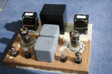
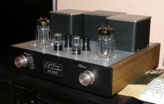
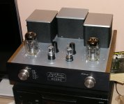
The amp is almost finished. I must install some source LED, the IR sensor and the foot.
All the adjustment are ok the voltage are correct like in the specs,
I love the sound of this amplifier.
Good luck to all who want to make this amplifier
The amp is almost finished. I must install some source LED, the IR sensor and the foot.
All the adjustment are ok the voltage are correct like in the specs,
I love the sound of this amplifier.
Good luck to all who want to make this amplifier
Attachments
Hi
The amp is almost finished. I must install some source LED, the IR sensor and the foot.
All the adjustment are ok the voltage are correct like in the specs,
I love the sound of this amplifier.
Good luck to all who want to make this amplifier
Hi Gabriel,
Congrats, nice work! Wish you to enjoy sonic beauty of your amp as much as possible.
And yes, since you finished first, now you are "prejudged" to be our "info-eldorado" 😉

Cheers,
Congratulations Gabriel. Excellent job!
Let us know how it sounds and give us more advise on the experiences you have had while building it.
Regards.
José
Let us know how it sounds and give us more advise on the experiences you have had while building it.
Regards.
José
Hi Gabriel,
Yes, I have now all the parts except the 4 big capacitors for the power supply filtering, that I am expecting from the USA. I will receive them probably one of this days because they were sent last Tuesday, but with the problems on the air traffic, I don't know.
Anyway, I have a lot of things to do with putting in place all the other components and the supports for these capacitors are already installed, as well as the big pieces like transformers and coils.
I have made myself a module to delay the high voltage of 2 minutes. I need to test it before install it.
By the way, I have a question about the earth and the separate ground in the Borbely's diagram (amplification part fig 4):
C5, C2 and D1-D3 are connected to the earth, which means to chassis; and all the other parts to the ground (0 volt). What is the use of this? Because if I understood well, the ground is connected to the earth through the 0 of the output transformers.
Can you or anyone else explain please?
Thanks.
Regards.
José
Hi
For this amp I use pcb design I don’t like the point to point system.
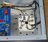
Those capacitors and zener diode are exactly like in the diagram to the ground of the amplifier. I use stellar ground. All the ground is in one point on the enclosure.
For this amp I use pcb design I don’t like the point to point system.
Those capacitors and zener diode are exactly like in the diagram to the ground of the amplifier. I use stellar ground. All the ground is in one point on the enclosure.
Hi Jose
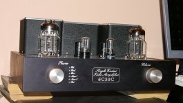
My amp runing all day long I love it.
I have in mind to start the second project in the same design, maybe a PP with 6C33C or a paralel SE but i am not shure witch tube to use for the project.
My amp runing all day long I love it.
I have in mind to start the second project in the same design, maybe a PP with 6C33C or a paralel SE but i am not shure witch tube to use for the project.
very nice job! congrats!!Hi
The amp is almost finished. I must install some source LED, the IR sensor and the foot.
All the adjustment are ok the voltage are correct like in the specs,
I love the sound of this amplifier.
Good luck to all who want to make this amplifier

would you mind to point me to the scheme of the amp... i wasn't able to find it... thanks!
- Status
- Not open for further replies.
- Home
- Amplifiers
- Tubes / Valves
- 6C33C-B. PP or SE ?