I think that Gabriel wants to say and can say that many combinations in the secondary voltage of anodes 6C33C.
Attach Schedule power transformer designs recommended for Gabriel.
The transformer is calculated for two channels with SE 6C33C.
I do not think a smaller section would meet the technical requirements of the amplifier.
Thanks for your attention!
Attach Schedule power transformer designs recommended for Gabriel.
The transformer is calculated for two channels with SE 6C33C.
I do not think a smaller section would meet the technical requirements of the amplifier.
Thanks for your attention!
Attachments
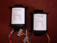
I apologize, but the design is sent to a mistake.Data secondary tensions are the following combinations:
1 to 2 = 160V
0 to 2 = 170V
1 to 3 = 180V
0 to 4 = 190V
These combinations offer a great opportunity to test various supply voltages for Ua (6C33C)
I apologize for the mistake!
1 to 2 = 160V
0 to 2 = 170V
1 to 3 = 180V
0 to 4 = 190V
These combinations offer a great opportunity to test various supply voltages for Ua (6C33C)
I apologize for the mistake!
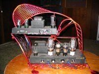
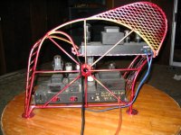
Thanks Dan. We were just talking about Concertina last night as a good approach. I am in the middle of an amp build right now, But this looks good for my next one. The tricky part will be stuffing it into this amp stand I build a could years ago. I would do the signal path on top with 4 6C33C tubes across the front and the power supply on the bottom. or vice versa depending on layout.
I sold the Hogan amps that were on there so the stand sits empty.
I sold the Hogan amps that were on there so the stand sits empty.
6C33C - PP-Amp von Ernst Roessler
it is a classic schematic : nothing new from the last 80 years about this but what a delight for listen to the MUSIC !
Just a hint : use Concertina or Cathode Coupled and NOT Paraphase for phase splitting instead .
Or even Williamson schematic with 6c33c at 180V...200V anodic +B 1 and separate 300V anodic +B 2 for the rest of tube.
( 250V it is a little to much for 6c33c )
Will be amazed ..... !
Attachments

Hi Gabriel,
Your amp looks a real profesionnal one!! Very good job!!
It makes dream.
Let us know the final tests.
Regards.
José
Your amp looks a real profesionnal one!! Very good job!!
It makes dream.
Let us know the final tests.
Regards.
José
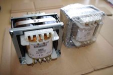
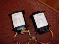
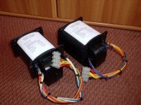
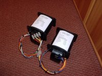
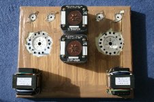
Nice transformers, can you tell us a price for a pair and also some specs?
I will show you my brother transformers. those trafo are big 15.5cm height.
I will show you my brother transformers. those trafo are big 15.5cm height.
Attachments
Hi Gabriel,Nice transformers, can you tell us a price for a pair and also some specs?
I will show you my brother transformers. those trafo are big 15.5cm height.
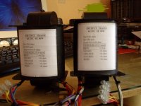
about price & specs please ask Mr. Ogonowski or see his site (http://www.ogonowski.eu/).
Your brother's OTs are also very impressive. Please, can you tell us
something more about that? Interesting core...
Cheers,
Hi all,
I stumbled across this thread and thought I would read it to find if anybody else had maybe built the same amp I did. I can not recommend this direct coupled design highly enough. I notice K.A.B is familiar with this amp.
About 4 years ago after much research and correspondance with the designer,
Ari Polisois, I built his DCMB ( direct coupled modulated bias ) amp with 6SN7as driver and with the 6C33C cathode direct to ground, made possible by using 2 power supplies and using an output trannie of my own design, the details of which are with the transformer company that wound the bobbins for me. I chose an input impedance of 1000 ohms which in practice worked well and allows me to use 4 to 8 ohm speakers. We once paralleled 4 ohm speakers for a party !
At the time some friends and I decided to build with the 6C33C, each choosing a different design. 2 were built with cap coupling, 1 Loftin White dc as appeared in Glass Audio magazine and mine
The first 2 sounded really good compared to other contenders, EL34 SE, KT66 etc. The Loftin White was way better but everybody agreed,some reluctantly, that mine sounded exceptional and the comparison ground to a halt. That is we did not need to go back and listen again to any others.
The excitement grew and it became a case of trying different speakers. Old Quad electrostatics sounded better than I had ever heard them and had the owners jaw on the floor !
The amp was bought by a friend and has been in daily use for three years. I intend building another when circumstances change. This thing grabs any speaker and makes it sound good, with a delightfull midrange and involuntary involvement with the music. Conventional amps sound boring, constipated and lifeless. No washed out thin wimpy sound here, this has a ballsy sound that puts a smile on your face and gets feet tapping. In other words MUSIC
Ari was very helpful when I emailed him on many occasions. His design can be found googling SIMPLEX DCMB
Regards Charles
Bas, thank you!
Cheers,
Hi all,
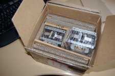
I have received the output transformers and the chokes (I put 2 chokes, even if I make a stereo configuration). The PS transformer will be ready next week.
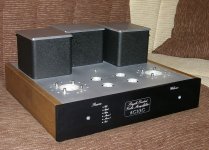
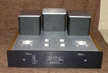
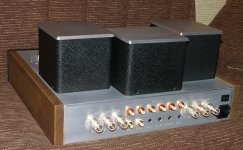
I wantted to ask your opinion about the best location on top of the chassis. For this, I post 2 pictures and I would appreciate which one do you prefer to place the PST, knowing that the free espace for it is in the middle for picture one or in the back for picture 2.
In advance thanks.
Regards.
José
I have received the output transformers and the chokes (I put 2 chokes, even if I make a stereo configuration). The PS transformer will be ready next week.
I wantted to ask your opinion about the best location on top of the chassis. For this, I post 2 pictures and I would appreciate which one do you prefer to place the PST, knowing that the free espace for it is in the middle for picture one or in the back for picture 2.
In advance thanks.
Regards.
José
Attachments

I´d put the output trannies near the corners and the power tubes.
The power supply in the rear between the power tubes to keep a little distance from the input tubes, and the chokes out in front, since they might be electronically quieter.
So I guess I´ll vote for version 2
The power supply in the rear between the power tubes to keep a little distance from the input tubes, and the chokes out in front, since they might be electronically quieter.
So I guess I´ll vote for version 2
Thanks Trondareo for your answer. I appreciate very much.
So, you prefer the configuration of the picture placed at the right? In which the OTs are already placed at the rear corners, the chokes in the middle, between the tubes, and the fre space between the OTs will be occupied by the PST.
This way, the PST will have less electronical impact on the rest!?
Regards.
Jose
Jepp, just make sure you turn the PST 90 degrees to the OTs to reduce inductive coupling between them. (assuming it is an EI transformer) Morgan Jones writes about the problem you are working on in the first chapter of "Building Valve Amplifiers"
OK, I think you're right. I'll go this way, even if my PST will be an encapsulated one, from Electra Sud-Ouest, and they told me that this kind of transformer doesn't produce any electronical influence.
Regards.
José
Regards.
José
PLEASE HELP!!!
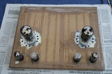
Hi all, I have started to solder the parts, according to the Borbely's schematics, which is the project I have adopted, and I am having an issue to determin the right pins' connecxion on the 6c33c-b socket.
The sockets I have bought are not marked with the numbers of the pins. If I understood well, the pin with the bigger hole is the pin number 4 ?? Now, if I look to the UNDER PART OF THE SOCKET, where I must solder the parts, where is the pin number 5, at the right or at the left of the bigger hole pin (number 4??)???
In advance thanks.
Regards.
Jose
- Status
- Not open for further replies.
- Home
- Amplifiers
- Tubes / Valves
- 6C33C-B. PP or SE ?