You may want to unhook the lower MOSFET from your circuit and test to see that is has not failed and is shorted from drain to source. I hope not, but that is one logical explanation.
From what I understand Rds should be infinity with no power.
Mine 1.5M with an Ohmmeter.
Regards,
Dan
This is my 'current dilemma' if you'll excuse the pun? 😛
I think I've overlooked something because my lower mosfet is acting like a light switch. I raise the bias until it 'turns on'. At that point it's a dead short and the full 3.2 amps flow through the circuit. What puzzles me is the lower mosfet doesn't warm up even one degree. Stone cold.
Regards,
Dan
you need to start biasing from low Ugs voltage , gradually opening lower mosfet
in a moment where its effective static impedance ( call it that way) is adequate , you'll have same voltage sag across both mosfets
now, Ugs is too high, lower mosfet is too open, so effective impedance is too small, so no voltage sag across it
in a moment where its effective static impedance ( call it that way) is adequate , you'll have same voltage sag across both mosfets
now, Ugs is too high, lower mosfet is too open, so effective impedance is too small, so no voltage sag across it
you need to start biasing from low Ugs voltage , gradually opening lower mosfet
in a moment where its effective static impedance ( call it that way) is adequate , you'll have same voltage sag across both mosfets
now, Ugs is too high, lower mosfet is too open, so effective impedance is too small, so no voltage sag across it
That does make sense to me. I have to figure out why I cannot achieve that as of yet. Either a flaw in my circuit design or a flaw in my approach.
More later.....................🙂
what's range of biasing voltage you can get from min to max?
how you made it, in first place , biasing circ?
how you made it, in first place , biasing circ?
what's range of biasing voltage you can get from min to max?
how you made it, in first place , biasing circ?
For the time being I'm using a separate lab (0-30vdc 3 a) power supply for biasing.
Regards,
Dan
taht's the problem, most likely - not fine enough management with pot on lab supply
make external rsistive divider :
set lab supply to - say +6V
put one leg of 5K trimpot on +6V , wiper to mosfet biasing , 3rd leg of trimpot to 4K7 resistor , other end of resistor to GND , where neg leg of Lab Supply is also connected
that way you'll have 5K trimpot span between +3V and +6V
Lab Supply is OK for many things, but its setting pot must be impeccable, or you're risking major ookups
Buddy of mine sent one THF to Wakan Tanka, while doing matching work - his new Lab Supply had twitchy voltage pot ......... and he didn't had fuse in drain etc.
luckily - you have there upper half of amp working as current limiter, instead of you being blasted across the room with bigchunkofplastic, which was functional mosfet few moments ago
taht's the problem, most likely - not fine enough management with pot on lab supply
make external rsistive divider :
set lab supply to - say +6V
put one leg of 5K trimpot on +6V , wiper to mosfet biasing , 3rd leg of trimpot to 4K7 resistor , other end of resistor to GND , where neg leg of Lab Supply is also connected
that way you'll have 5K trimpot span between +3V and +6V
Lab Supply is OK for many things, but its setting pot must be impeccable, or you're risking major ookups
Buddy of mine sent one THF to Wakan Tanka, while doing matching work - his new Lab Supply had twitchy voltage pot ......... and he didn't had fuse in drain etc.
luckily - you have there upper half of amp working as current limiter, instead of you being blasted across the room with bigchunkofplastic, which was functional mosfet few moments ago
Will try soon! Many thanks Zen.
Regards,
Dan 🙂
of course, if that sounds too much of work, just use Car Jack for biasing
try with smaller one ........

try with smaller one ........
of course, if that sounds too much of work, just use Car Jack for biasing
try with smaller one ........
I'm half blind too, but I can still 'see' good advice when I get it.

Little bit of drifting but Vds1=Vds2.
Many thanks to ZenMod for the solution to my problem! 🙂🙂🙂🙂🙂🙂🙂🙂🙂🙂
so, it works now?
Haven’t put a signal through it yet and won’t have time for a while. I’m now at the point where I can’t see any reason it won’t work.
Once again, many thanks to the Mighty ZM! 🙂
considering that I'm Omnipresent and Omnipotent, as usual, feel free to rephrase that:
Once again, mighty tnx to Many ZM!
....... keep us informed , and just double trimpot-resistor arrangement for second channel biasing
Once again, mighty tnx to Many ZM!
....... keep us informed , and just double trimpot-resistor arrangement for second channel biasing
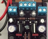
I sure bit off a lot to chew on. I did my own PCBs for most of the PS and all of the amplifier. I also built my own single chassis out what I thought were large enough heat sinks but small fans may be in my future.
What’s that old saying? What doesn’t kill you makes you stronger? 😉
Well it will make me stronger because it wouldn’t surprise me if the final
edition weigh 100lbs!
A couple of quick pics later today.
Regards,
Dan
What’s that old saying? What doesn’t kill you makes you stronger? 😉
Well it will make me stronger because it wouldn’t surprise me if the final
edition weigh 100lbs!
A couple of quick pics later today.
Regards,
Dan
To ground or not to ground? That is the great question?
In the process of getting my multi kilowatt schade ready I'm now testing
my 2sk170/2sj74 buffer I included at the input. As seen in the pic below I have a separate +/-12 supply for powering my buffers. The question that puzzles me is should I tie the ground of my buffer supply to the ground of my main amplifier supply? 😕
Attachments
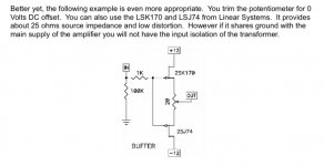
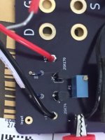
I'm also assuming if I choose to go 'ungrounded' my unbalanced inputs ground will be that of the buffers ground.
Regards,
Dan
Regards,
Dan
you must connect buffer GND and amp GND
both of my legs are able to walk, but they're best doing that when still connected at my hips
both of my legs are able to walk, but they're best doing that when still connected at my hips
- Home
- Amplifiers
- Pass Labs
- 50w Single-Ended BAF2015 Schade Enabled