Somewhere in my pile o' stuff I have some huge "ashtray style" IGBTs from Fuji or the like, purchased in a spirit of speculation from an Ebay retailer that parts out monster motor drives - their huge, reasonably priced heat sinks have featured prominently in various of my class A projects. So, IGBTs are not great on linearity by themselves, but in a "buffered Schade" implementation with a P-channel mosfet to provide some drive, maybe we can break the 50W barrier for a simple Class A single ended amp, with some decent sound along the way. One man's trash is another man's treasure...
Hello President FAB
I would like to see that.
https://en.wikipedia.org/wiki/Common_gate
The P-channel mosfet sourcefollower/buffer provides current gain and the common gate n-channel (Jfet in this schematic) provides voltage gain. The feedback loop to the Jfet gate is a normal Schade feedback. If the Schade-feedback resistor voltage devider is connected before the output capacitor it can be used to bias the N-channel device (enhanced mode).
Cheers,
Johannes
We can use a gain device in its most absolutely linear and stable mode: Common-Gate (or Common-Base, Common-Grid). In other words, we should cascode the output of the DAC chip. In Common-Gate mode (in the case of a Fet) we attach the Gate to ground (or at least an AC ground) and send the input to the Source pin. The Source pin has is a relatively low impedance, more or less the inverse of the transconductance of the gain device, which satisfies one of the conditions that a current source DAC is looking for. Given the nature of the Fet and the high output impedance of the DAC chip, all the current output of the DAC will appear at the Drain of the Fet and will be driven through some value of resistance to deliver an output voltage.
The very nature of Common-Gate mode insures the absolutely lowest distortion and widest bandwidth possible. It is not often used because its input impedance is very low, but in this case it's a natural.
From Nelson Pass article http://www.firstwatt.com/pdf/art_zen_iv.pdf
I think he describes the potential benefits with the common gate much better then I could, so I just quote him here.
Cheers,
Johannes
https://en.wikipedia.org/wiki/Common_gate
The P-channel mosfet sourcefollower/buffer provides current gain and the common gate n-channel (Jfet in this schematic) provides voltage gain.
Cheers,
Johannes
Like I/V converter?

This is the schematic of the amp playing Cristobal Tapia de Veer as I type this post.

A simple point to point test with some devices bolted to a piece of 15 mm alu plate.
I had something different in mind, but each to his own...
I'm guessing you mean p channel buffer at input.
I had something different in mind, but each to his own...
There are many ways to do this.
I'm guessing you mean p channel buffer at input.
I am using a p channel buffer at input, but I prefer using the source of the n channel device as input node since it is usually much more linear and has much higher bandwidth then the gate.
In my experience the common source circuit is the worst in pretty much every way, except pure simplicity since you only need one single active device to build an amp. A common drain coupled to a common gate is much more linear and has much higher bandwidth with the same type of devices. With a common gate you evade much of the gate to source capacitance, with is a large contributor to the total amount of distortion in the amp, and especially so at high frequencies.
Nelson Pass often writes that he does not consider a cascode device to be a another gain-stage, since all it does is shield the gain-device from the voltage variations drain to source. It does not contribute much of its own character to the amp. I guess it is much more of a voltage-regulator to fix some voltage at a more useful value. (Sweetspot article)
Since a common drain (sourcefollower) is the most linear way to use a gain-device, it is quite logical to use a common gate cascode device to create voltage gain and shield the common drain from large voltage variations. The p channel buffer is perfectly suited to amplify the amount of current needed, so with a very low impedance high current, low voltage output, it seems very strange and mismatched to drive a many hundred mega Ohm non-linear gate instead of the very linear and low impedance source of the main gain device.
This is my reasoning behind this circuit, "but each to his own" as you say...
🙂
Cheers,
Johannes
Neither do I, that's just not the road I'm traveling. If I can find my IGBTs without having to shift the whole house, I'll post a picture of them - they're beastly.
I like picture books. 😀
An externally hosted image should be here but it was not working when we last tested it.

I like those Cree devices. The best part is the "Ease of paralleling" in the spec sheet. 😀
I can imagine a 2 kW cacoded version of the BAF2015. Say 700 volt powersupply and 100 ampere of constant current... The local steel plant would complain of reduced voltage to their electric arc blast furnace available from the powerplant whenever you fire up our surround system... 😀
Better to live near a large lake so you can watercool the amps. No more Ice-skating wintertime though....
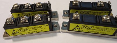
For more than 20 years I've been meaning to do something
with my supply of these.
Do I see a 100 watt Schaded SoZ on the horizon?
Cheers,
Johannes
View attachment 550812
I like those Cree devices. The best part is the "Ease of paralleling" in the spec sheet. 😀
I can imagine a 2 kW cacoded version of the BAF2015. Say 700 volt powersupply and 100 ampere of constant current... The local steel plant would complain of reduced voltage to their electric arc blast furnace available from the powerplant whenever you fire up our surround system... 😀
Better to live near a large lake so you can watercool the amps. No more Ice-skating wintertime though....
You might need to build yourself a nuclear reactor first to power it. 😀
Because of you, I just came up with a brilliant idea for a different project.
These ideas always seem to come when on the toilet. Don't ask why.
Hahahaha
- Home
- Amplifiers
- Pass Labs
- 50w Single-Ended BAF2015 Schade Enabled