Actually in retrospect I think it would be a good idea to remove the output tube sockets, and just put big round holes in the PCB where the output tubes go. That way you could wire in whatever tube and socket that you want, octal, magnoval, compactron...
What do folks think about that idea? Good, or dumb?
Pete
Another thing I would consider is not using PCB traces for the filament wiring. I am considering an SMPS for the DCPP filaments given what I perceive the 6CB6 susceptibility to picking up hum.
Easily cured with a Dremel tool in the present case.
There are many of these TV-tubes with varying filament voltages which can be configured as both need and opportunity arise.
As a follow-up -- the DCPP uses ~ 40W on the filaments. In series with a tweaked-up off the shelf SMPS power supply that's 8 x 6.3V heaters, or 4 in the case of the monoblock discussed here. Lots of inexpensive OEM solutions which could be affixed to the bottom of a Hammond chassis under the HV trafo.
I like the idea of being able to use different heater voltages. Perhaps two separate connections one for the output tubes and one set for the input section. Or else 4. Either way that would be great. For instance I have some 12bq6gt's and I think I bought a bunch of 2GU5s a while back thinking I could use those in place of the 6GU5 in my stereo red board. Never got around to that though just used the 6GU5's since I didn't feel like cutting any traces at that time.
Actually in retrospect I think it would be a good idea to remove the output tube sockets, and just put big round holes in the PCB where the output tubes go. That way you could wire in whatever tube and socket that you want, octal, magnoval, compactron...
What do folks think about that idea? Good, or dumb?
Right;
it is a real engineer's decision to open a path for convection!

Forum member W5JAG took a Greenlee to an SSE board and has shown pictures with several different sockets and tubes in it. Most are in this thread. Near the end you will see a 4 pin socket in one channel and a 5 pin in the other.
http://www.diyaudio.com/forums/tubelab/291593-tubelab-se-removing-mosfets.html
I simply left the 12 pin compactron sockets in my red board and stacked an octal or magnoval socket on top of it with its pins spread out. I then ran wires to the appropriate spot on the board for each pin. I started out with octal sockets wired in a manner that allowed the largest number of possible tube choices, then rewired for the next combination after trying all the compatible tubes.
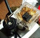
I use a socket adapter for pin configuring the curve tracer. Push-on single pin sockets have wires going to banana plugs to fit the tracer. Heat shrink tubing is placed over the single pin sockets. The single pin sockets fit noval pins, so they work with 7 pin, 9 pin, novar, and compactron bases. (but not octal or magnoval) So I have a home made adapter from octal to compactron base.
Could put such wire/socket pins dirctly on the PC board (banana plugs not needed)
Would be super if there are direct tube socket to wire wrap pin type sockets around. The single pin sockets could just push-on to the wire wrap pins then.
Could reverse that for normal tube sockets, I suppose. Put a row of labeled wire wrap pins on the board, and each type of tube socket gets short wires with single pin sockets on the wire ends. Plug them onto the board according to pin-out.
..
Attachments
Would be super if there are direct tube socket to wire wrap pin type sockets around. The single pin sockets could just push-on to the wire wrap pins then.
Wire-wrap -- was it Steve Ciarcia who termed it "knitting for electrical engineers" ?
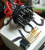
If one could find some single pins that fit an octal socket, could just put an octal socket directly on the board. Then wire a socket adapter to short wired single pins.
Unfortunately, the old headphone single pin plugs/jacks don't fit octal sockets, so some new pin type needs to be found.
Unfortunately, the old headphone single pin plugs/jacks don't fit octal sockets, so some new pin type needs to be found.
Actually in retrospect I think it would be a good idea to remove the output tube sockets, and just put big round holes in the PCB where the output tubes go. That way you could wire in whatever tube and socket that you want, octal, magnoval, compactron...
What do folks think about that idea? Good, or dumb?
Pete
Terrific idea.
Win W5JAG
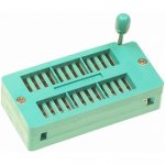
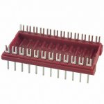
Could put a 24 pin IC ZIF socket on the board for each tube, and make the tube socket adapters wire up to a 24 pin DIP header. Dedicate 2 or 3 IC pins for each tube element for reliability and current handling, with some insulating guard pins around the plate and screen pin(s).
Could even skip the DIP header, and just put some stiff wires on the tube socket, bent into position to fit the ZIF socket. Would give a whole new meaning to "integrated" tube amp. Filament current might be a problem without redundant contacts however. Someone needs to come out with a ZIF tube socket.
Could even skip the DIP header, and just put some stiff wires on the tube socket, bent into position to fit the ZIF socket. Would give a whole new meaning to "integrated" tube amp. Filament current might be a problem without redundant contacts however. Someone needs to come out with a ZIF tube socket.
Attachments
Last edited:
Whatever board that may or may not come of this discussion. I just want to say the most alluring aspect of this monoblock is the CAD files and top mount adjustments with meters. This makes it easier to make adjustments with plastic screwdrivers with minimal exposure to the chassis underneath. When dealing with high voltage this seems preferable to the DCPP from a noob perspective.
If one could find some single pins that fit an octal socket, could just put an octal socket directly on the board.
Perhaps those IDE drives' power connector female plugs might fit?
Best regards!
Whatever board that may or may not come of this discussion. I just want to say the most alluring aspect of this monoblock is the CAD files and top mount adjustments with meters. This makes it easier to make adjustments with plastic screwdrivers with minimal exposure to the chassis underneath. When dealing with high voltage this seems preferable to the DCPP from a noob perspective.
The trimmer potentiometers which Pete specified allow adjustment from top or bottom -- so I drilled 3/16 holes in the chassis where specified.
You can use Pomona or Cinch panel mount "tip jack" or "pin jack" for monitoring the DC bias and balance potentiometers. Available from all the usual suspects and most electronic surplus outlets.
Unlikely to get tubes which are "matched" so you'll often find that you're swapping in different compactrons or drivers until you get the THD% down to the advertised levels.
Attachments
Another thing I would consider is not using PCB traces for the filament wiring.
I like that idea, too. Wouldn't be hard - each filament trace could have a jumper in the trace. Jumper in - normal filaments. Jumper out - use the pad nearest the tube to bring in whatever voltage you want. Might get double utility by using the jumpers to span other traces.
Win W5JAG
board and schematic says 6CB6 ........
website says 6GU5 tube for the input/driver, which is a beam hexode, wired as a
pentode ?
very confusing for non-experts
website says 6GU5 tube for the input/driver, which is a beam hexode, wired as a
pentode ?
very confusing for non-experts
board and schematic says 6CB6 ........website says 6GU5 tube
When Pete designed the original amp I got one.....then 2 more. I have stuffed just about everything that would fit into the sockets, and wired on additional sockets and repeated the exercise.
I tried dozens of different pin compatible tubes into the input sockets. The original amp was specified to use 6CB6's, and they work fine in that amp or this one. When we started squeezing the design to see what we could get out of it (about 250 watts per channel) we needed an input tube with more gain.
The 6GU5 provided a bit more gain, and lowered the overall distortion too. It is a drop in for either amp and may work better. My suggestion.....get some of each and see what sounds best to you. They both work fine, along with at least a dozen others.
- Home
- Vendor's Bazaar
- 50W monoblock "Engineers Amp"