the figure of merit for me is transconductance when it comes to choosing input stage tubes...
to me any tube is only as good as its cathodes...
to me any tube is only as good as its cathodes...
6CB6 Gm = 8000
6GU5 Gm = 15000
The 6EW6 may be another good choice at 14000 but I didn't have enough good ones to make a valid comparison when I did all the tube rolling through the Big Red Board.
High Gm requires a cathode that can keep the space charge filled regardless of how hard the plate drains it, but Gm is largely determined by the G1 to cathode spacing, and the pitch and diameter of the grid wires. That's why the frame grid was such an improvement.
6GU5 Gm = 15000
The 6EW6 may be another good choice at 14000 but I didn't have enough good ones to make a valid comparison when I did all the tube rolling through the Big Red Board.
to me any tube is only as good as its cathodes...
High Gm requires a cathode that can keep the space charge filled regardless of how hard the plate drains it, but Gm is largely determined by the G1 to cathode spacing, and the pitch and diameter of the grid wires. That's why the frame grid was such an improvement.
The 6EW6 may be another good choice at 14000 but I didn't have enough good ones to make a valid comparison when I did all the tube rolling through the Big Red Board.
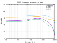
Based on your input on an old thread I tried 6EW6s in my DCCP. I've yet to write all this up (or indeed trace where the difference between channels comes from) but here is a frequency response comparing 6EW6s to 6CB6.
As one would expect, with the greater gain there is more to feedback, therefore flatter response?
I've no idea on the distortion levels, but tuning it in using an FFT to get as low spikes at 2kHz and 3kHz sounds good to me.
I was hoping to get more output from the DCCP by using more sensitive driver tubes as my sources are below line-level (see http://www.diyaudio.com/forums/tubes-valves/309518-active-bax-preamp-6db-gain-design-critique.html)
Attachments
All of my testing was done with the local (plate to plate) feedback only. I never needed or liked any GNFB in my versions, even the 125 WPC flavor. The 6GU5 provided the most gain, which was needed to get to 125 WPC.
The gain in this amp is influenced by the Gm of the tubes, the plate load resistor in the input tube, the plate to plate feedback resistor, and GNFB if used. I tweaked the first three, and left out the GNFB to suit my needs for the 125 WPC version. The stock version probably has enough gain for most applications as designed, or slightly boosted by swapping tubes with the stock parts values. I didn't (and still don't) have enough 6EW6's to give them a fair test, and all of mine are used.
My working board still has the 6GU5's in it from when I built it. I swiped the output tubes, but I have more. It is now getting a new home inside a PC, a rather unusual PC with a Lexan window to show off the tube stuff of course. It also has a guitar jack!
I wanted to build this (2 mono blocks) and I assumed it's going to be easy. I bought 2 PCB and all parts, 6 tubes each from Pete, spent lots of time building the box from scratch (only one). Did not bother to try amp outside the box (what can go wrong?).
Measured voltages without tubes, all good (bit higher lik +425 instead of +407 but that was to be expected).
Inserted tubes, power ON, tubes glow but the bias voltages are over 1V so I shut down power and turn trimmers a bit clockwise. Power ON, no glow, power OFF, blown main fuse.
Pulled off tubes, changed fuse, power ON, voltages OK. Put in 6GU5s, fuse blown.Changed fuse, pulled out 6GU5s, put in 6HJ5s, fuse blown. Arghhhhhhhhhhh.
New fuse, new 6GU5s, no 6HJ5s, power ON, tubes glow, all OK!
power off, put in 6HJ5s, power ON, fuse blown.
Last fuse.
all tubes out.
Voltage check: all seems OK.
New 6HJ5s in, power ON, tubes glow.
Power off, new (last) 6GU5s in, power ON, fuse blown.
End of story, no more fuses (should probably start this with tested and true light bulb in line with power - too late now).
Any ideas why this is happening.

I wanted to build this (2 mono blocks) and I assumed it's going to be easy. <snip>.
very interesting that fuse is always blowing at turn off, is that right?
I was not clear enough: fuses blow on power ON.
These fuses are (were) 2A 250V, should not blow even if they are fast (or not?)
These fuses are (were) 2A 250V, should not blow even if they are fast (or not?)
should not blow even if they are fast (or not?) .....Pete's BOM calls for 2A slow blow
A tube amp, particularly one with solid state rectifiers can be expected to draw a huge turn on current. The tubes are all cold, thus their heater current will be 2 to 4 X the nominal draw for the first few seconds, and the capacitors are all discharged. There is no slow warm up on SS diodes, those hungry caps look like a dead short for the first few milliseconds with the current only limited by the DCR in the power transformer. That's why we use slow blow fuses and inrush current limiters.
Try the correct fuse before going any further.
Fast fuses!!!! Arghhhh. Thank you so much for the advice. I had a bunch of fuses and assumed they are "normal" slow ones. Went today and bought "slow" ones and learned that the new "normal" is "fast".
BTW, I have my bias voltage not fully stable: instead of being 500mV (50mA) i get from 490 to 550mV
BTW, I have my bias voltage not fully stable: instead of being 500mV (50mA) i get from 490 to 550mV
I'm building two (2) of Pete's Monoblock versions of the DCPP and am having some difficulty figuring out where to buy the in-chassis heat sink that either mounts to or passes through the top plate of the chassis. Pete's web page describes it but I was wondering if any of you having built the project can tell me your source of this part of the heat sink? I plan on using a couple of Parts-Express.com Shure heat sinks, Part #DC-HS11123 or Part #DC-HS11118 for the exposed part of the enclosure, do you guys know where to source the in-chassis part of the heat sink the MOSFETs are mounted to? Would appreciate any input, thanks!
JWags911SC,
Did you figure out how to implement the heat sink? I’m just starting on a couple monoblocks and have the same question.
Did you figure out how to implement the heat sink? I’m just starting on a couple monoblocks and have the same question.
Heatsinks
I found out from Pete that he employed Heat sinks from HeatsinkUSA.com and ordered a couple that I need to anodize. I was advised to use a common L shaped aluminum angle to attach the devices inside the chassis, so I just need to order the aluminum angle, then I plan on drilling through the top plate and secure the top heat sink through the chassis and the aluminum angle. I have a tap and die set already, so this shouldn't be much of a challenge. I hope this helps steer you in the right direction.
I found out from Pete that he employed Heat sinks from HeatsinkUSA.com and ordered a couple that I need to anodize. I was advised to use a common L shaped aluminum angle to attach the devices inside the chassis, so I just need to order the aluminum angle, then I plan on drilling through the top plate and secure the top heat sink through the chassis and the aluminum angle. I have a tap and die set already, so this shouldn't be much of a challenge. I hope this helps steer you in the right direction.
JWags911SC,
Thanks. That does help. If I'm reading the mechanical drawings correctly, the aluminum angle should be 1" x 2" x 3" with 1/8" walls. Google tells me that is a less common size, though I did find it at onlinemetals.com. Unfortunately, they don't offer that size in anodized stock. Is the anodization important?
mike
I don't believe that the aluminum angle has to be anodized, the only reason I can think you may want it anodized would be to make sure it is electrically insulated from the three components mounted to it. I don't know if this would be to prevent the degradation of the audio signal, or if it pertains to safety. I plan on anodizing mine at the same time I do the heat sinks since I am doing it in house.
As I was getting ready to purchase this board I realized that unlike the original this mono version does not have plate cap holes. Is there an easy way around this? Also, is there any chance of a new version with minor revisions?
1. Plate cap connection
2. Separate heaters connections for the driver and output tubes (with a jumper if both are the same voltage)
3. Removal of sockets. That way the standoff screws don't need to be so long.
Last question revolves around how the amp actually works. Does the driver contribute to the max wattage that this amp can produce or does it merely provide gain? If it's just gain then I assume that the Aikido preamp I am building would allow me to use much lower transconductance tubes than a 6GU5 (want to try octals).
Right, I have ordered a couple of boards and am going to try to build these beauties. The Mouser list is useful, as they have a UK site and it translates the prices automatically.
My only question (at this stage - I'm sure there will be a few later) is concerning the substitution of parts for UK use.
Is it only the power transformer that needs to be changed, for 240 volt UK supply?
My only question (at this stage - I'm sure there will be a few later) is concerning the substitution of parts for UK use.
Is it only the power transformer that needs to be changed, for 240 volt UK supply?
Hello .. hope you are well
Just one question what are your plans for sourcing the valves ? have you a UK supplier or ebay / or directly from peter's web site
Just one question what are your plans for sourcing the valves ? have you a UK supplier or ebay / or directly from peter's web site
- Home
- Vendor's Bazaar
- 50W monoblock "Engineers Amp"