You can also use a Zobel network in a lot of similar instances, the resistor can be made to appear in parallel at frequencies above the audio band if desired. (Typically I use something like 0.1uF - 0.22uF and 33 ohm resistors)
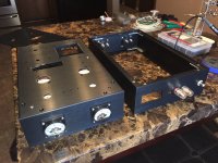
Thanks for all the feedback on your builds. I did get my chassis in this week. Spent a few days trying to find all the proper hardware. Ended up using #6-32 by 9/16th stand offs. Unfortunate I ended up breaking two thread taps in my heat sinks and pretty much destroying the pieces trying to remove the broke off taps. So rather than trying to sand them down I opted to order a couple new heat sinks and plan to have the machine shop drill and tap them for me this week.
I am very happy with the work that Landfall Systems did on the chassis. Those guys really delivered. If I had it to do over though, I probably would have ask them to make the chassis just a half inch taller to allow for a little more room between the pcb and the meters.
I am very happy with the work that Landfall Systems did on the chassis. Those guys really delivered. If I had it to do over though, I probably would have ask them to make the chassis just a half inch taller to allow for a little more room between the pcb and the meters.
Last edited:
If the current goes up when connecting a particular speaker, with no audio, it's likely that it is oscillating due to some reactive component of the load. Usually if you place a dummy resistor load of between 20 and 100 ohms across the output, it fixes it...
Pete
Thanks, Pete. Will try this next. I was initially thinking/hoping it could have been caused by the increased capacitance or inductance from coiling the extra length of speaker wire...that was not the case.
Another anomaly......I received and installed the higher resolution LED volt meters. I've been noticing the bias never really seems to settle down into a steady state and it ever slowly continues to increase. The amps have about 10hours on them now, so I don't believe this is a component burn in issue. Both monoblocks behave similarly. I measured bias1, bias2, SG and C- over the period of 3 hours, every 15 minutes. Measurements taken with input shorted and 10R load on 8-ohm tap. See results below.
Is this normal? How long (warm up time or break in hours) should it take for bias current to settle in? Any other thoughts?
BIAS1 (V), BIAS2 (V), -C (V), SG (V)
0.416 0.399 -80.0 146 (initial turn on)
0.488 0.492 -80.5 148.1
0.513 0.517 -80.6 149.7
0.524 0.530 -80.6 150.4
0.532 0.538 -80.7 150.9
0.541 0.549 -80.5 151.1
0.543 0.551 -80.6 151.4
0.549 0.557 -80.6 151.5
0.551 0.559 -80.5 151.6
0.553 0.562 -80.5 151.7
0.556 0.566 -80.5 151.8
0.550 0.561 -80.8 151.9 (here I thought it finally settled in)
0.564 0.576 -80.2 151.8
0.563 0.575 -80.3 151.9
I had a similar issue, I biased mine to a fraction below 0.400 after 1 hour, then re-biased them a couple of days later. So now on turn on they are about 0.300 and warm up to around 0.500 after about half an hour, mine settle around this level. I also swapped out R13 and R14 for 47k.
I also spent a bit of time matching tubes, that helped as well.
Sorry for the late response, I saw your post and was itching to respond, but I was in the game reserve and the mobile connectivity was very bad.
I also spent a bit of time matching tubes, that helped as well.
Sorry for the late response, I saw your post and was itching to respond, but I was in the game reserve and the mobile connectivity was very bad.
Last edited:
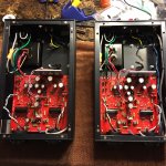
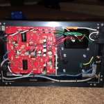
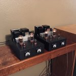
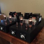
So I finally have mine finished after a couple frustrating weeks. Definitely worth the headaches. (mostly self imposed) They sound clean, articulate and powerful. No shortage of low end either. Will post some pictures tomorrow.
Here are a few pictures of the finished product. Due to space issues I had to mount the bias meters on the outside of the chassis. I am still looking for an alternative 0-1v bias meter. These ali express units do not seem to be very accurate.
Attachments

These ali express units do not seem to be very accurate.
I think I got lucky only one of my units was slightly out, but you can adjust the calibration with the screw on the front, you just need to turn it really slowly. I basically attached all of mine (in parallel) to the same constant known voltage in order to do the calibration.
Hi kolakidd,
That screw adjust is for zero. The span calibration is done with a resistor, there should be one inside the meter in series with it. You can short that resistor out and put one outside with a slightly lower resistance, then use a variable resistor in series with that so you can calibrate the meter exactly. What you have done is thrown the poor calibration out and made one that might be accurate at your one voltage.
So again, with power off set your zero with the screw, then back it off a touch to prevent the screw from moving the zero during a temperature change. The full scale reading is set with a variable resistance. Then your meters should be pretty accurate.
-Chris
Hi kolakidd,
Once you find out what the value of the internal resistor is, let us know and we can suggest a new value for the resistor and a variable pot. You could actually mount the new resistor where the old one goes and then mount the control outside so you can calibrate each meter with a minimum of stuff hanging around outside the meter.
-Chris
So I’ve noticed that these mono blocks (or at least my build) gets very hot after several hours of use. Much as I like the chassis there really is no air vents in the bottom cover. Do you think I should remove the bottom cover entirely or maybe cut vent holes into it? The other option I was considering was simply setting a small fan next to the units.
My DCPP gets very hot and uncomfortable to touch - over 65deg on the surface of the chassis according to my thermal camera. So I got a new chassis with vents top and bottom to encourage natural convection. That made a slight improvement, but the real improvement was when I mounted a computer fan below the unit (cut a hole in the shelf) and ran it slowly. Forced convection means the chassis is warm but not burny-hot.
T
T
Hi kolakidd,
Once you find out what the value of the internal resistor is, let us know and we can suggest a new value for the resistor and a variable pot. You could actually mount the new resistor where the old one goes and then mount the control outside so you can calibrate each meter with a minimum of stuff hanging around outside the meter.
-Chris
Hey Chris, I'm not going to be opening these up any time soon, I will when I do something major. Getting them out means removing the board and all the associated fiddling, which is no small task. I've also got a way more accurate way of biasing, I installed some breadboard cables in parallel with the meters, hidden just under the amp chassis, so what I do is plug in a couple of wires and hook the amp up to a picoscope and do a quick calibration if the meters ever look out of whack.
Obviously, there is always the OCD element, so I might hit aliex in a couple of days and just order some new ones. If I do I'll definitely post values
Hi kolakidd,
If they read high, you just need to use a pot in series to calibrate them. That would be easy. Otherwise by taking out the original resistor and replacing it with a lower value, you are forcing it to read high. Then you use a pot to calibrate it.
-Chris
If they read high, you just need to use a pot in series to calibrate them. That would be easy. Otherwise by taking out the original resistor and replacing it with a lower value, you are forcing it to read high. Then you use a pot to calibrate it.
-Chris
So I’ve noticed that these mono blocks (or at least my build) gets very hot after several hours of use. Much as I like the chassis there really is no air vents in the bottom cover. Do you think I should remove the bottom cover entirely or maybe cut vent holes into it? The other option I was considering was simply setting a small fan next to the units.
My chassis has no base, my unit does get hot, but not so much that I would put in a fan.
Hi kolakidd,
If they read high, you just need to use a pot in series to calibrate them. That would be easy. Otherwise by taking out the original resistor and replacing it with a lower value, you are forcing it to read high. Then you use a pot to calibrate it.
-Chris
Okay, you've convinced me I'll put a pot in series, I also want to check if the units can actually be opened. I had a quick look at my photographs and I think they are actually sealed.
- Home
- Vendor's Bazaar
- 50W monoblock "Engineers Amp"