Was the squarewave plot with feedback or without, and a nominal non-inductive resistor load? Assuming it was with feedback, then at least the amp is stable in that condition. I can see the original comments in post #55 on stability. Are you using the original output transformer? Did you attempt to improve the damped ringing on the squarewave with capacitance across the feedback resistor (a small radio tuning capacitor is quite practical for that role) ?
Welcome to the world of stability compensation!
Welcome to the world of stability compensation!
Both the square wave and bode plot were without feedback into a 10W wire-wound resistor. I'm using toroidal output transformers. I'll checkout #55.
I'll try it with a small amount of feedback tomorrow.
I'll try it with a small amount of feedback tomorrow.
Since you're new at measuring open loop gain and stability, suggest some practice with op amps, high pass and low pass filters etc. Take an opamp and drive a capacitative load to see what you should be looking for.
Suggestion -- before measuring make sure that your test setup is linear, standardize!. Poor test probes in particular can make phase measurement problematic.
Suggestion -- before measuring make sure that your test setup is linear, standardize!. Poor test probes in particular can make phase measurement problematic.

As per post #55 I've done testing with and without the 33pF capacitor. These are without:


The 2 peaks in the frequency response at ~110kHz and ~190kHz are visible in the square wave response. The ~110kHz ripple is higher amplitude than Pete's result in post #55.
These are with the 33pF capacitor

The second peak is much reduced and the square wave response does look better:

Nearly as good as Pete's result in post #55. I'd go with that but...
I replaced the 8Ω load with 1k. Very shortly after the square wave appeared on the output, a screen full of HF oscillation appeared and I quickly powered-down.
I'll do more testing.
The 2 peaks in the frequency response at ~110kHz and ~190kHz are visible in the square wave response. The ~110kHz ripple is higher amplitude than Pete's result in post #55.
These are with the 33pF capacitor
The second peak is much reduced and the square wave response does look better:
Nearly as good as Pete's result in post #55. I'd go with that but...
I replaced the 8Ω load with 1k. Very shortly after the square wave appeared on the output, a screen full of HF oscillation appeared and I quickly powered-down.
I'll do more testing.
Attachments
GNFB Problem Post - 2
Hi. I’m looking for some compensation advice. Given the oscillation caused by the 33pF lead compensation I’ve investigated lag compensation but I can’t get a result like that in post #55 or in the reference mentioned below.
Here are some results with 330pF and 22k between the anodes of the differential pair. 10kHz response looks like this


Slew rate is ~0.5V/us.
1kHz looks like this (actually 47k but 22k is similar

It takes 200us to settle.
I really tried to do the job properly using the approach described in Amplifier Compensation - Prevent Oscillation and overshoot in Negative Feedback Loops, but was never able to construct a Bode diagram as described. I had to resort to trial and error.
The amp doesn’t oscillate into a 1k load.
What are the pros and cons of using the lag compensation described vs no compensation as shown below?

Hi. I’m looking for some compensation advice. Given the oscillation caused by the 33pF lead compensation I’ve investigated lag compensation but I can’t get a result like that in post #55 or in the reference mentioned below.
Here are some results with 330pF and 22k between the anodes of the differential pair. 10kHz response looks like this
Slew rate is ~0.5V/us.
1kHz looks like this (actually 47k but 22k is similar
It takes 200us to settle.
I really tried to do the job properly using the approach described in Amplifier Compensation - Prevent Oscillation and overshoot in Negative Feedback Loops, but was never able to construct a Bode diagram as described. I had to resort to trial and error.
The amp doesn’t oscillate into a 1k load.
What are the pros and cons of using the lag compensation described vs no compensation as shown below?
Imho, every output transformer is likely a new endeavour, especially if the aim is for stable operation not just with no load, but also with capacitance only loading.
Were you able to confirm (eg. by a quick waveform capture) that the 1k load hf oscillation occurring in post #345 was below 150kHz, as it may be related to the ~150kHz resonance blip seen in the plot with rated load. You may be able to obtain a spectrum plot with say 100 ohm load such that the amp is stable, but there is a brewing resonance peak forming at the hf oscillation frequency.
If that was the concerning resonance frequency for no load conditions then that allows some awareness of what techniques may be useful to suppress gain or phase shift out at say 150kHz. However it's likely that curtailing forward gain by networks such as the 330pF-22k (corner of 22kHz) then encroach on the audio range, reducing feedback in the treble or higher region.
Not all forms of compensation hold the same benefit for different amps, as sometimes oscillation can occur at higher frequencies than what can be discerned up to 150kHz, and the resonances can move around due to the loading conditions (rated R load, no load, and cap only loading).
Often a compensation cap across the feedback R can improve squarewave response with rated load, and can be 'dialed in' for a great squarewave. But that comp cap may bite you on the bum when trying for stability with no load or cap only loading, and may be related to letting too much signal through at higher up resonances. That may be a reason for sometimes seeing the feedback resistor split into two, with separate comp caps.
Sometimes peaky response above 100kHz with no load, or cap only loading, can be alleviated with an output RC zobel that aims to present a load R at such higher frequencies where the peaking is a problem. It is just one option, but luckily doesn't require a high voltage cap. Another option is to lower forward gain using a comp cap across the 100k leaks in the output stage.
The impact on forward gain of a compensation technique can be measured by comparing gain-phase plots with no feedback, as gain may need to be rolled off down towards 10kHz such that sufficient roll-off has occurred out at the oscillation resonance. That is part of the trial and error with say lowering the 330pF-22k corner to see if that can achieve stable operation.
Last edited:
Thanks. I'll do more gain/phase plots.
With 33pf across the feedback resistor, it oscillated with a 100Ω load too. I need to try some lower value resistors to find the resonance peak.
I've just started measuring the other channel. With the 33pF across the feedback resistor, it doesn't seem to exhibit the same resonance issues. I need to find the cause of the difference. Audio band gains are very close.
No compensation

33pF lead compensation

Differences in the OPTs?
With 33pf across the feedback resistor, it oscillated with a 100Ω load too. I need to try some lower value resistors to find the resonance peak.
I've just started measuring the other channel. With the 33pF across the feedback resistor, it doesn't seem to exhibit the same resonance issues. I need to find the cause of the difference. Audio band gains are very close.
No compensation
33pF lead compensation
Differences in the OPTs?
Were those plots from the other channel?
Difference in OPT's may be difficult to assess, as that perhaps needs an actual swap - so that all other variables remain the same.
Difference in OPT's may be difficult to assess, as that perhaps needs an actual swap - so that all other variables remain the same.
They were both from the other channel. I've taken both channels back to uncompensated. In that state they're close to identical. Left channel again

and right channel

I'll redo all the amplitude and phase vs frequency charts again. Laborious but needs to be done.
At this point I'm leaning towards omitting the compensation. In use the amp will have balanced inputs. the input transformers are 3dB down at 100kHz. There's not going to be high levels of HF coming out of my DAC.
and right channel
I'll redo all the amplitude and phase vs frequency charts again. Laborious but needs to be done.
At this point I'm leaning towards omitting the compensation. In use the amp will have balanced inputs. the input transformers are 3dB down at 100kHz. There's not going to be high levels of HF coming out of my DAC.
Thank-you trobbins for your posts above and in the Oscillations in tube amps thread.
After re-reading all your posts I decided to have another read of Amplifier Compensation - Prevent Oscillation and overshoot in Negative Feedback Loops and it all finally made sense.
I followed the procedure described and calculated that I needed lag compensation between the anodes of the differential pair of 62k and 63pF, and lead compensation of 26pF across the feedback resistor.
With 11.6dB of feedback, gain is 20.6dB.
10kHz square wave output for the 2 channels now looks like this:

and

I’m happy with those. The slew rate looks to be slightly more than 0.5V/us.

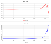
Gain and phase look good with the gain flat to 20kHz and 3dB down at 140kHz.
Unfortunately, there’s still oscillation with no load, but it doesn’t lead to blown fuses or the high voltage regulator current limiting.

Frequency is slightly less than 1MHz. There's no HF oscillation with no input but there is a 0.75Hz 1.5V RMS LF oscillation.
I’ll have to modify my PCB to accommodate the lag compensation components.
Before that I’ll do distortion measurements which I’ll post here.
After re-reading all your posts I decided to have another read of Amplifier Compensation - Prevent Oscillation and overshoot in Negative Feedback Loops and it all finally made sense.
I followed the procedure described and calculated that I needed lag compensation between the anodes of the differential pair of 62k and 63pF, and lead compensation of 26pF across the feedback resistor.
With 11.6dB of feedback, gain is 20.6dB.
10kHz square wave output for the 2 channels now looks like this:
and
I’m happy with those. The slew rate looks to be slightly more than 0.5V/us.
Gain and phase look good with the gain flat to 20kHz and 3dB down at 140kHz.
Unfortunately, there’s still oscillation with no load, but it doesn’t lead to blown fuses or the high voltage regulator current limiting.
Frequency is slightly less than 1MHz. There's no HF oscillation with no input but there is a 0.75Hz 1.5V RMS LF oscillation.
I’ll have to modify my PCB to accommodate the lag compensation components.
Before that I’ll do distortion measurements which I’ll post here.
- Home
- Vendor's Bazaar
- 50W monoblock "Engineers Amp"