Hello,
I'm starting to plan my build of the 50W monoblock "Engineers Amp". Pcb's have been purchased and I'm starting to collect parts. As a possible alternative power transformer, I found the Antek AS-4T320, but it has a 70V tap instead of the 60V on the Hammond. Can this be made to work? Any other problems with using this transformer?
https://www.antekinc.com/as-4t320-400va-320v-transformer/
@audiorasp See post #13 in this thread: https://audiokarma.org/forums/index...milletts-50w-monoblock-engineers-amp.1003445/
jeff
jeff
My high power Engineers amps oscillate when I apply global negative feedback (GNFB)
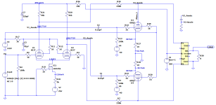
I’ve attached the schematic of my 100W Engineer’s amplifier without GNFB.
High power mods are as described by tubelab and Michelag in posts #263 and #277.
Differential/driver stage tubes are 6EJ7. Output transformers are 3.3kΩ toroidals.
The 550V supplies, actually, 530V, are regulated by 21st Century Maida regulators. Bias is managed by a bias servo.
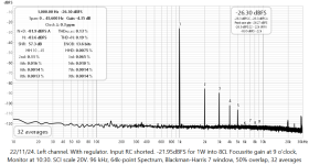
Without negative global negative feedback, the 2 amps work and measure just fine. 1kHz THD is 0.13% at 1W and 0.27% at 25W.
I thought I’d try GNFB using the feedback network in the original schematic.

Both amps oscillated, one in 1kHz modulated HF bursts while the other one blew the on-board fuse AND its Maida regulator.
Not entirely surprising given that the 6EJ7s are higher gain tubes I suppose.
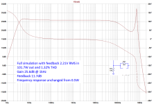
I played around with my LTSpice simulation and with the original feedback network, gain was down from the open loop 37.5dB to -0.124dB which is puzzling.
I tried a simple feedback network instead and the simulation worked much better.

Putting even 10pF in parallel with R34 increased a peak in the frequency response at around 700kHz.
I tried that in the amps and it worked there too. 10kHz square wave response was very rounded though. More testing and measurements required.
I did re-read the relevant sections of “Valve Amplifiers”, third edition, but talk of poles, zeros and fudging the phase/amplitude response is way over my head.
Any advice anyone can offer would be much appreciated.
I’ve attached the schematic of my 100W Engineer’s amplifier without GNFB.
High power mods are as described by tubelab and Michelag in posts #263 and #277.
Differential/driver stage tubes are 6EJ7. Output transformers are 3.3kΩ toroidals.
The 550V supplies, actually, 530V, are regulated by 21st Century Maida regulators. Bias is managed by a bias servo.
Without negative global negative feedback, the 2 amps work and measure just fine. 1kHz THD is 0.13% at 1W and 0.27% at 25W.
I thought I’d try GNFB using the feedback network in the original schematic.
Both amps oscillated, one in 1kHz modulated HF bursts while the other one blew the on-board fuse AND its Maida regulator.
Not entirely surprising given that the 6EJ7s are higher gain tubes I suppose.
I played around with my LTSpice simulation and with the original feedback network, gain was down from the open loop 37.5dB to -0.124dB which is puzzling.
I tried a simple feedback network instead and the simulation worked much better.
Putting even 10pF in parallel with R34 increased a peak in the frequency response at around 700kHz.
I tried that in the amps and it worked there too. 10kHz square wave response was very rounded though. More testing and measurements required.
I did re-read the relevant sections of “Valve Amplifiers”, third edition, but talk of poles, zeros and fudging the phase/amplitude response is way over my head.
Any advice anyone can offer would be much appreciated.
Attachments
I've not found spice to be very useful when it comes to stability. Too hard to model all the parasitics in the OPT.
My guess (and it's just a guess) is that the toroidal OPTs have a lot of interwinding (and intrawinding) capacitance. That could have a big effect.
You can try and make open loop gain and phase measurements, that may point you in a direction.
That said, a rounded waveform on a 10kHz square wave is probably not a bad thing, assuming the freq response is OK. A rounded 10kHz square wave just means that the amp is rolling off at ultrasonic frequencies. 1KHz should look pretty square.
Pete

Doing open-loop gain-phase, and then with a low level of feedback, may identify a rising magnitude resonance peak, and phase deviation, related to the onset of oscillation with increased feedback if it was related to output transformer or other hf resonance. Without the ability to make gain-phase out to say 1MHz, then a squarewave response may adequately indicate a rising magnitude peak's frequency and damping response.
A quick capture of a scope waveform showing actual oscillation is also worthwhile trying to obtain for post-assessment. Perhaps see if that can be done in a way that minimises collateral damage, such as time to capture the waveform, and a variac to operate below nominal rail levels, and with a standard matched resistor load (before starting to advance to no-load and worst-case loading performance).
A quick capture of a scope waveform showing actual oscillation is also worthwhile trying to obtain for post-assessment. Perhaps see if that can be done in a way that minimises collateral damage, such as time to capture the waveform, and a variac to operate below nominal rail levels, and with a standard matched resistor load (before starting to advance to no-load and worst-case loading performance).
As Pete mentions, the model for a toroid OPT is going to sim much differently than Hammond or Edcor.I've not found spice to be very useful when it comes to stability. Too hard to model all the parasitics in the OPT.
My guess (and it's just a guess) is that the toroidal OPTs have a lot of interwinding (and intrawinding) capacitance. That could have a big effect.
Here's a "how to" apnote on measuring transformer characteristics. https://www.omicron-lab.com/fileadm...ling/App_Note_Transformer_modelling_V_2_0.pdf
You don't need a kilobuck network analyzer, (like the Bode-100), you can use a sweep generator and your 'scope (triggered) but you'll have to do the maths on your own.
The problem with Toroidal transformers is that they can't control the windings very well, the centre bunches. So you get variations between transformers of the same number. So a Toroidal output transformer is a bad idea. As a power transformer, I'll stick with E-I thank you very much!
Thanks for the feedback. As soon as I've replaced the blown regulator I'll start doing some open loop measurements.
Thanks also for the App Note.
Thanks also for the App Note.
A few of us are using a Picoscope and free FRA4PS software to make gain-phase sweeps to 1MHz to assist stability assessment and managing output transformer resonances. My Picoscope was 10% of the Bode-100 pricetag, but still a big purchase.Here's a "how to" apnote on measuring transformer characteristics. https://www.omicron-lab.com/fileadm...ling/App_Note_Transformer_modelling_V_2_0.pdf
You don't need a kilobuck network analyzer, (like the Bode-100)....
I'd suggest a fast squarewave input and a scope with bandwidth to at least 10MHz may well be the lowest cost and easiest way to ascertain the frequency of a resonance that leads to unstable oscillation due to GNFB, and the benefit of adding typical compensation (such as cap across feedback resistor). The characteristic of the leading edge waveform can tell a lot. Knowing what frequency is the first hurdle to adjusting known compensation methods like a step network, or adding a zobel.

My cheap Rigol oscilloscope is up for that.A few of us are using a Picoscope and free FRA4PS software to make gain-phase sweeps to 1MHz to assist stability assessment and managing output transformer resonances. My Picoscope was 10% of the Bode-100 pricetag, but still a big purchase.
I'd suggest a fast squarewave input and a scope with bandwidth to at least 10MHz may well be the lowest cost and easiest way to ascertain the frequency of a resonance that leads to unstable oscillation due to GNFB, and the benefit of adding typical compensation (such as cap across feedback resistor). The characteristic of the leading edge waveform can tell a lot. Knowing what frequency is the first hurdle to adjusting known compensation methods like a step network, or adding a zobel.
If the Rigol was 8-bit then that may limit dynamic range to 42dB max for gain-phase sweeps, so a bit less than 40dB if some allowance for headroom, and some further allowance for LF or HF peaking, so perhaps allows plotting to -25 to -30dB below midband. But well worth deploying to identify peaking and first major resonances 👍. I went for 12 bit, so a bit more expensive. Hopefully your Rigol software makes it easy to do sweeps.
The 1MHz generator in the Picoscope is suitably fast for squarewave generation for my normal audio testing, and I've recently used the scope to identify an 807 related resonance just above 1MHz sitting on a squarewave response.
The 1MHz generator in the Picoscope is suitably fast for squarewave generation for my normal audio testing, and I've recently used the scope to identify an 807 related resonance just above 1MHz sitting on a squarewave response.
Ordinarily, the HT does not need regulation.I'm not using Pete's power supply. Both the HT and screen supplies are regulated.
Some folk using a Maida regulator have bypassed the output capacitor with a film cap. This can cause issues with output impedance. Topic for a new thread.
Absolutely!
Most regulators are amplifiers internally and do not deal with low impedance at high frequencies very well at all. Read the manufacturers spec sheet. Many used to show a stability graph with output capacitance, read the text in the data sheet carefully, and app notes too.
Most regulators are amplifiers internally and do not deal with low impedance at high frequencies very well at all. Read the manufacturers spec sheet. Many used to show a stability graph with output capacitance, read the text in the data sheet carefully, and app notes too.
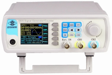
New 21st Century Maida Regulator installed and tested and cute new JDS6615 signal generator received from China (the brand name Junctek is ominous).
The plan was to use the signal generator's sweep function to to generate an amplitude vs frequency plot on my Rigol oscilloscope. A simple sweep from 10Hz to 10MHz.
That's on hold until I work out whether it's possible to restart a sweep from its set starting frequency. Default seems to be to keep running the sweep forever. If I stop it, it restarts at the frequency it stopped. Very weird. I even tried switching the generator off and on and it still remembers that frequency! There's PC control software but I'm having problems with that too.
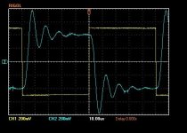
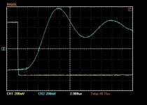
Anyway, I'll sort that out later. it generates an acceptable looking 10kHz square wave.
The 2 oscilloscope shots show the input (yellow) and amp output (blue).
The ripple on the square wave peaks looks to be 100kHz. Any suggestions as to what that might mean for the negative feedback components?
The plan was to use the signal generator's sweep function to to generate an amplitude vs frequency plot on my Rigol oscilloscope. A simple sweep from 10Hz to 10MHz.
That's on hold until I work out whether it's possible to restart a sweep from its set starting frequency. Default seems to be to keep running the sweep forever. If I stop it, it restarts at the frequency it stopped. Very weird. I even tried switching the generator off and on and it still remembers that frequency! There's PC control software but I'm having problems with that too.
Anyway, I'll sort that out later. it generates an acceptable looking 10kHz square wave.
The 2 oscilloscope shots show the input (yellow) and amp output (blue).
The ripple on the square wave peaks looks to be 100kHz. Any suggestions as to what that might mean for the negative feedback components?
Attachments
- Home
- Vendor's Bazaar
- 50W monoblock "Engineers Amp"