Mark,... But in your specification there are three issues that should be corrected, clarified.
First, you use incorrect pin numbers. ETD49 bobbin has pin #1 in the left top corner, and the numbering goes counterclockwise. The pin numbers are even written on the top of the bobbin. Your numbering is "mirrored". It is not a problem if you wind the transformer on your own. But if you give this specification to a professional company, as a result you will get "mirrored" version of the transformer. Such a transformer cannot be used with the board you designed. So pin #10 on your drawing is actually pin #1, pin #20 is pin #11, and so on.... It means also that the pin numbers on the schematic are also incorrect. Do you see it? ...
At the time of drawing the schematic I didn't have specs or pin numbering for the Epcos coilformer. Only this datasheet with no such details.
So, as for the trafo specs pdf you may take into consideration the "top view of the pcb" detail and do the proper numerotation. According with your coilformer notation.
Regards, Geani.
Hi,
these are specific to wrap your transformer.
are the synthesis becouse not have the necessary parameters, wire type, inductance, etc ...but contains procedures for safety
I hope I have been of help to some.
I do not recommend DIY on transformer.
Regards
these are specific to wrap your transformer.
are the synthesis becouse not have the necessary parameters, wire type, inductance, etc ...but contains procedures for safety
I hope I have been of help to some.
I do not recommend DIY on transformer.
Regards
Attachments
Looks good. It's worth to notice that this is BOTTOM VIEW (at the pin numbers are OK).
You reversed the beginning of L3 + L4 but you also reversed the direction of winding (clockwise). So I think the results are the same as I wanted it to do (as long as L3 and L4 are in the same direction).
Can you give some more details of the copper ring?
Mark
You reversed the beginning of L3 + L4 but you also reversed the direction of winding (clockwise). So I think the results are the same as I wanted it to do (as long as L3 and L4 are in the same direction).
Can you give some more details of the copper ring?
Mark
Hi,
yes, L3-L4 runs contrary becouse direction is inverse. Result same.
copper foil, this ring suppresses the flow outside of the transformer. can also be very often to dispose of some of the heat (not in this case).
important that the width is within the margins of the spool (5 +5 mm from the edges).
this transformer can be built in 20 different ways, but these...are trade secrets🙂
Regards
Op
I totally Agree with you
Hi,
copper foil, this ring suppresses the flow outside of the transformer. can also be very often to dispose of some of the heat (not in this case).
important that the width is within the margins of the spool (5 +5 mm from the edges).
this transformer can be built in 20 different ways, but these...are trade secrets🙂
Regards
I totally Agree with you
Yes
But please note that this is NOT any ordinary DIY where a schematic is shown
In which case only skilled would consider to build it
Its been stated that there will not be a schematic, only "commercial" boards to buy
And the designers obviously want people to buy, and build it
Its not just a DIY project
Such approach always attracts lesser skilled that it maybe shouldnt
Thats where the danger is
I still suggest any issues to be cleared
If it results in yet another redesign, so be it
Thats not my concern, only safety is
Any issues should be noted, right or wrong
Either way, argumentation should be relatively easy
tinitus,
We have presented schematic, bom and gerber files during this thread.
http://www.diyaudio.com/forums/power-supplies/149702-50v-smps-quasar-amps-others-4.html#post1913849
SMPS schematic ver2 is mainly the same, but based on people feedback we have added lot of features and options in order to satisfy a large area of diy projects, from SS amplifiers up to tubes.
Current version will be presented to diy community as soon we will go to next version.
Regards,
Tibi
Edit later:
Above schematic link is broken. Here is the new one http://vicol-audio.ro/products/smps/pictures/SMPS_-+50v_rev1.0.pdf
Last edited by a moderator:
Hi,
these are specific to wrap your transformer.
are the synthesis becouse not have the necessary parameters, wire type, inductance, etc ...but contains procedures for safety
I hope I have been of help to some.
I do not recommend DIY on transformer.
Regards
AP2,
Thanks for your time and work !
Regards,
Tibi
My SMPS SMPS ver2 at work. I manage to get 280V and 2x15V. The SMPS is still under test. The goal is to obtain 350V/0,5A , 2x12V/10A
reading on 500V scale
An externally hosted image should be here but it was not working when we last tested it.
reading on 500V scale
An externally hosted image should be here but it was not working when we last tested it.
+/- 50 volt smps design.
I am not sure if this has been posted, I apologize if it has. I came across this on the internet and thought I would pass it along. No reason you could not use a voltage doubler on the input for 120 volt mains. The IR2110 could be replaced with a transformer.
I am not sure if this has been posted, I apologize if it has. I came across this on the internet and thought I would pass it along. No reason you could not use a voltage doubler on the input for 120 volt mains. The IR2110 could be replaced with a transformer.
Attachments
Last edited:
In case you haven't noticed, this thread is on specific SMPS project and not on any power supply.Here is another one I found, looks like a good bench supply for amp work. ETD49 core in full bridge mode should be good for over 1kw. Anyone want to draw up a board for it?
The second schematic is widely known SMPS from A-and-T company (you can easily find it on the Internet). And if you are from the States, you can buy either a printed board for this SMPS or buy it as a kit (with all components). Drawing a new board for this power supply does not make sense. But please create a separate thread for this if you need.
Mark
While waiting for the transformer (already ordered), may I ask for some clarifications of other issues? I need information regarding R12 and D13 diode/s.
1. Tibi, you promissed translation of Romanian comments on the schematic. It's high time to do it. Here is the first remark regarding R12:
"Sursa functioneaza fara probleme cu R12 acolo unde este plasata in schema.
Insa, dupa un test a reiesit ca sursa e mai stabila daca rezistenta se monteaza in locul indicat!
Atentie. NU se monteaza 2 rezistente, ci doar se muta R12, daca se doreste."
I assume that instead of soldering R12 between pin 1 and the ground, you solder it in series - from U5 to pin 1 U3. And you have to cut the trace to do it, right? What was the reason?
2. Second remark - D13:
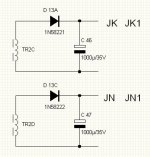
"Placa suporta 2 tipuri de conexiune: a). 2 diode independente, notate D13A & D13C (1N5822);
b) o singura dioda, cu anod comun (in principal, pt varianta sursa filamente), notate D13A & D13B (MBR3045). In acest caz, se inchide conexiunea la Jp3"
I need +/-15V and I have MBR3045. I thought that it's simple but when I look at the fact that MBR is "common-cathode" and not as you write "anode comun", and that you put a "MBR40xx" symbol at D13A diode and "MBR30xx" symbol at D13B and they have common cathode I'm getting confused. Additionally, I'd say that jumper4 should be shorted and not jumper3. Can you clarify this?
Mark
1. Tibi, you promissed translation of Romanian comments on the schematic. It's high time to do it. Here is the first remark regarding R12:
"Sursa functioneaza fara probleme cu R12 acolo unde este plasata in schema.
Insa, dupa un test a reiesit ca sursa e mai stabila daca rezistenta se monteaza in locul indicat!
Atentie. NU se monteaza 2 rezistente, ci doar se muta R12, daca se doreste."
I assume that instead of soldering R12 between pin 1 and the ground, you solder it in series - from U5 to pin 1 U3. And you have to cut the trace to do it, right? What was the reason?
2. Second remark - D13:
"Placa suporta 2 tipuri de conexiune: a). 2 diode independente, notate D13A & D13C (1N5822);
b) o singura dioda, cu anod comun (in principal, pt varianta sursa filamente), notate D13A & D13B (MBR3045). In acest caz, se inchide conexiunea la Jp3"
I need +/-15V and I have MBR3045. I thought that it's simple but when I look at the fact that MBR is "common-cathode" and not as you write "anode comun", and that you put a "MBR40xx" symbol at D13A diode and "MBR30xx" symbol at D13B and they have common cathode I'm getting confused. Additionally, I'd say that jumper4 should be shorted and not jumper3. Can you clarify this?
Mark
Last edited:
"Sursa functioneaza fara probleme cu R12 acolo unde este plasata in schema.
Insa, dupa un test a reiesit ca sursa e mai stabila daca rezistenta se monteaza in locul indicat!
Atentie. NU se monteaza 2 rezistente, ci doar se muta R12, daca se doreste."
the source work without a problem with R12 placed like in the schematic. After a test, result that the source works better with R12 placed in the pointed place on the schematic.
Beware. DO NOT place 2 resistors, only move R12 , if you want.
"I assume that instead of soldering R12 between pin 1 and the ground, you solder it in series - from U5 to pin 1 U3. And you have to cat the trace to do it, right? What was the reason?" ur assumptions r right
"Placa suporta 2 tipuri de conexiune: a). 2 diode independente, notate D13A & D13C (1N5822);
b) o singura dioda, cu anod comun (in principal, pt varianta sursa filamente), notate D13A & D13B (MBR3045). In acest caz, se inchide conexiunea la Jp3"
The PCB support two tipes of connexion a) 2 independent diode, D13A & D13C
b) only one diode, common anode ( mainly for filament source) D13A&D13B. In this case you will close Jp3.

Thanks Sere for the translation. But this does not answer to my questions. In my case, I need +/-15V and I have MBR3045. Can I use it? Which jumper should be shorted? Is it the diode common-anode or common-cathode? I see common-cathode on the schematic. What does it mean "mainly for filament source"? Can it be used "sometimes" for other power supplies?b) only one diode, common anode ( mainly for filament source) D13A&D13B. In this case you will close Jp3.
Tibi, any comments?
Mark
Markus2006 ..for +/-15V and MBR3045 u have to use two independent diodes(MBR3045) with anodes soldered together (MBR3045 is common cathode, TO-3 case, anode -pin1&2, cathode -case ) and JP4 closed.
"mainly for filament source" .. this way of making conections is intended to power tubes filament. Low voltage 6,3-12V & more current. When u close JP3, diodes ( windings to be precise) are paralleld. For tubes close jp3, JK-JL, JN-JO and you will have two unregulated filament sources. You can use it for other power supplies when you need bigger current, nondifferential voltage.
An externally hosted image should be here but it was not working when we last tested it.
"mainly for filament source" .. this way of making conections is intended to power tubes filament. Low voltage 6,3-12V & more current. When u close JP3, diodes ( windings to be precise) are paralleld. For tubes close jp3, JK-JL, JN-JO and you will have two unregulated filament sources. You can use it for other power supplies when you need bigger current, nondifferential voltage.
Last edited:
Hmm, the more you explain, the more I'm confused. MBR3045 is a double diode and it's not in TO-3 case but rather TO247.Markus2006 ..for +/-15V and MBR3045 u have to use two independent diodes(MBR3045) with anodes soldered together (MBR3045 is common cathode, TO-3 case, anode -pin1&2, cathode -case ) and JP4 closed.
You can see it here: Expresie c?utat?: MBR3045 // Elemente ?i piese electronice componente - TME ? Electronic Components
Are you trying to say that MBR3045 cannot be used for +/-15V power supply, or what? I'm guessing that the Jumper4 should be closed (Jp3 open) and I should use real independent diodes, like e.g. 1N5822: Expresie c?utat?: 1N5822 // Elemente ?i piese electronice componente - TME ? Electronic Components
I don't need high current. Most probably it will be 100-200mA.
Mark
- Home
- Amplifiers
- Power Supplies
- ±50V SMPS for Quasar Amps (& others)