to Tvicol.
copy this .. if you can understand how it works🙂
😛
This is what I am talking about, You should tell us from where you got this design?
Dont tell me its yours!, Cos I saw that, and fixed one very close to it.
So dont ask VICOL to copy it, cos HE wont copy. Also do like vicol and post FREE design, NOT copied designs 😀
VICOL design is not a copy!
I also like that black box: hahahah
Whats inside it?
Last edited:
Thanks Microsim for the support 😀. I already contacted a professional company concerning this output transformer and they ask me several detailed questions because they want to make the transformer following some security rules. They build similar transformers on a daily basis so I assume they have a reason to ask. We need detailed information on the transformer. And since such order will take several days, I need the info as soon as possible.Markus2006
I can Agree with you, that Vicol must supply such details in a paper, that INDICATES exact winding process, wire size, winding order, Each winding = how many volts (so you can get the voltage you need).
Mark
You wrote that I wanted to copy probable, this is impossible, I have developed a new true tehcnologia for PSU (RIPS) and true innovation for class D amplifiers (MXD), and finally sounds can be measured as class AB.
you think I do I copy ...
best regards
you think I do I copy ...
best regards
Ha, ha. I've seen your Web site - is it audiopower.it? Very nice products but you have only 1 post on the forum, 17 visitors per day and most of the pages do not work (actually they do not even exist). Now I understand why you keep posting on this forum 😀. Do you see any similarities between Tibi's project (as you say not being professional) and your Web site 🙄?to Tvicol.
copy this .. if you can understand how it works🙂
Seriously, I assume that you have a lot of knowledge. Why don't you just share it with us instead of complaining? If there is anything wrong with this project, you can tell what is wrong and how to solve the problem. Otherwise, complaining makes not much sense for me. It's just a waste of time.
Mark
Web is not ready, audiopower not me, is holding marketingsu license who has developed new products.
I want to help those in difficulties, and would also help acap psu that sound very different from PE as you know it. (even big companies have no clear ideas), do not be surprised about that.
telling tvicol to post their project with the test, I thought it was serious and proper to do so. (not because I need the project)
corrections.
Web is not ready, audiopower not me, is marketing company under license from the developer of new products.
I want to help those in difficulties, and would also help to understand that psu for audio is very different from what you know. (even big companies have no clear ideas), do not be surprised about that.
telling tvicol to post their project with the test, I thought it was serious and proper to do so. (not because I need the project)
corrections.
I want to help those in difficulties, and would also help to understand that psu for audio is very different from what you know. (even big companies have no clear ideas), do not be surprised about that.
QUOTE]
Hahahahahh
Thats really amazing, I bit that you dont know the big companies either, or ever heard of it.
Tell us what is the defrence between AMPLIFIER SMPS, AND (What We Know) SMPS?
I assure you, that I have schematics that you never saw in your whole life!
Try to be logic man!
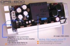
By the way, picture above for PFC, Or complete SMPS with PFC 700W?
Last edited:
Could we please keep on track here, instead of this
Its too dangerous to not take seriously
Microsim have been around that issue too
If theres any safety issues here, it should be adressed, properly
So please, could we focus on "safety first" here
Its too dangerous to not take seriously
Microsim have been around that issue too
If theres any safety issues here, it should be adressed, properly
So please, could we focus on "safety first" here
ok, I did not understand anything of life.
If you have innovative schemes, this is good.
Are you sure that I do not quite understand looking at?
I do not make the race ... who is better.
I have just created a psu with only 300uF at 70V to emulate 22000uF ... I think you know what that means.
If you have innovative schemes, this is good.
Are you sure that I do not quite understand looking at?
I do not make the race ... who is better.
I have just created a psu with only 300uF at 70V to emulate 22000uF ... I think you know what that means.
Now it makes sense what you are saying. Why didn't you say it from the very beginning?I want to help those in difficulties,
I'm interested but most probably this thread dedicated to specific SMPS is not good for this. You can create a new thread in the Power Supplies forum.and would also help to understand that psu for audio is very different from what you know. (even big companies have no clear ideas), do not be surprised about that.
I think that the easiest way to test this SMPS is to build it. Why don't you try it?telling tvicol to post their project with the test, I thought it was serious and proper to do so. (not because I need the project)
Mark
Could we please keep on track here, instead of this
Its too dangerous to not take seriously
Microsim have been around that issue too
If theres any safety issues here, it should be adressed, properly
So please, could we focus on "safety first" here
It all begins when you were asking I think about how many turns tvicol, (this is already wrong) becouse tvicol must post their project with relevant safety tests (if project is public). I saw that were wrong turns, I spoke, saying that 4 turn on regulator for entry is correct + / -15. perhaps tvcol has not calculated that even under curent burst, this voltage is modulated by PWM.
I remain of the view that the errors on the PCB show a lack of knowledge by putting people at risk.
tvicol sell through this forum its PCB and no one checks that at least is not dangerous to young people who have no experience. in italy this is prohibited by law.
o discuss new solutions, I am readily available, the true reason why I signed up here
If you want to be precise, it was me who was asking about turns for +/-15V winding. The numbers 2x2 were never posted before on this forum. And I've got this info in a private e-mail but I could interpret it icorrectly.It all begins when you were asking I think about how many turns tvicol, (this is already wrong) becouse tvicol must post their project with relevant safety tests (if project is public). I saw that were wrong turns, I spoke, saying that 4 turn on regulator for entry is correct + / -15. perhaps tvcol has not calculated that even under curent burst, this voltage is modulated by PWM.
Actual situation is that we are waiting for the output transformer specification. Somehow it is very difficult to get it.
And if you AP2 have something to add regarding safetly of the board, please do it. But please refer to the current version of the project.
I already suggested a new thread (e.g. regarding capacitance multiplyer in your SMPS).to discuss new solutions, I am readily available, the true reason why I signed up here
BTW, isn't every SMPS dangerous if you are not careful?
Mark
Only serious respectful behaviour will be tolerated from now on
Any possible issues needs to be treated seriously and with respect
Please respect that this is dangerous stuff, and have to be handeled accordingly
Poor behaviour and careless posting could turn it into being even more dangerous
Please think about this before posting
And yes, I suggest to be on hold, until its been proven to work properly and safely
Preferably by other skilled members
Its NOT a beginners project
OK
I totally AGREE tinitus
I think its over, Trying to power up this SMPS without proper saftey procedures, may cause sever damage to the PCB, and Lethal charge in the capacitors are capable of nasty SPARK (that may Cause permanent BLINDNESS), Either it will Kill you, Or Blow UP your fuse class on the FLY, and if you were looking at the fuse while blowing you are gone.
Friend, In my first SMPS prototype, I blow some mosfets, PCB Burned, FUSES blown on the sky.
Take care.
Fox
Only serious respectful behaviour will be tolerated from now on
Any possible issues needs to be treated seriously and with respect
Please respect that this is dangerous stuff, and have to be handeled accordingly
Poor behaviour and careless posting could turn it into being even more dangerous
Please think about this before posting
And yes, I suggest to be on hold, until its been proven to work properly and safely
Preferably by other skilled members
Its NOT a beginners project
I totally AGREE tinitus
I think its over, Trying to power up this SMPS without proper saftey procedures, may cause sever damage to the PCB, and Lethal charge in the capacitors are capable of nasty SPARK (that may Cause permanent BLINDNESS), Either it will Kill you, Or Blow UP your fuse class on the FLY, and if you were looking at the fuse while blowing you are gone.
Friend, In my first SMPS prototype, I blow some mosfets, PCB Burned, FUSES blown on the sky.
Take care.
Fox
Maybe this is boring but I need the specification of the output transformer. I talked to professional company that makes such transformers on a daily basis and they said that there is a (security) bug even on the first photo of the transformer, which shows the first part of the primary winding. You can see it here: http://www.diyaudio.com/forums/power-supplies/149702-50v-smps-quasar-amps-others-8.html#post2038195 - post #77.
The guy from the company says that one cannot connect end of the primary winding to the right side of the bobbin (due to security issues). All primary windings have to be connected to the left side of the bobbin (if they start there) and all secondary windings have to be connected to the right side. And you cannot mix "primary" side with "secondary" side - it's dangerous. So the photo shows it incorrectly.
It seems also to me (correct me if I'm wrong) that the pins of the bobbin are counted incorrectly. If you look at the bobbin from the top, pin #1 is in the left-top corner and the numbering goes counterclockwise. I think that the project assumes that it is clockwise starting from the left-bottom corner. As a result you may easily end up with a "mirror" version of the transformer.
There are also other security issues (like specific "security margin" between widings) that were not mentioned here. That's why I'm happy that I called professional company and ask for details. I recomend to order the output transformer from such a company. This is critical component of the SMPS.
That's why I will insist to get precise specification of the transformer taking also into account various security issues.
Mark
Hi,
to Mark.
is normal that the company asks the specifications of the transformer,
the specifications of a transformer, usually are 2 pages A4.
This means that it is not easy (it's easy when you look at it).
I examined the schematic and PCB (1-2 red solder).
the PSU can work ,is to be understood as a basic regulated SMPS, does not include soft-start, this may be a problem if there is a short-circuit during start-up.
does not include steps necessary to avoid introducing imd on amplifiers.
if can help you, PCB 1 and 2, do not have sufficient clearance (very too small) in the high-voltage area.
Even the arrangement of components in this area is not good.
this is my opinion. (pcb and trasf re-designed with appropriate knownow)
(even the wire to wrap the primary is wrong) this transformer has 2,67:1ratio. (wire-size) of the primary is not good.
If TVICOL adjust the PCB and publicate the measurements on amplifiers and test on security ... I think it can sell more.
regards
This is very well known fact. On page #17 I posted example specification from Power Integrations.Hi,
to Mark.
is normal that the company asks the specifications of the transformer,
the specifications of a transformer, usually are 2 pages A4.
The lack of soft-start may be a problem. Isn't SG3525 providing a kind of a soft-start?the PSU can work ,is to be understood as a basic regulated SMPS, does not include soft-start, this may be a problem if there is a short-circuit during start-up.
And how this information can possibly help me?if can help you, PCB 1 and 2, do not have sufficient clearance (very too small) in the high-voltage area.
Here you can help but instead of saying that everything is wrong, just say what wire should be used (and why).(even the wire to wrap the primary is wrong) this transformer has 2,67:1ratio. (wire-size) of the primary is not good.
General remark: you mentioned previously that the pads for high voltage capacitors are only 0.3 mm and the whole SMPS is going to explode on start-up. I checked that the pads are 4 mm and the tracks in this area are 5 mm or more. So your remarks until now are highly inaccurate. Please try to focus on what you are trying to say. Instead of saying that everything is wrong, try to tell how a specific problem can be solved.
Mark
- Home
- Amplifiers
- Power Supplies
- ±50V SMPS for Quasar Amps (& others)