Hi,
project is .. films with as many episodes😀
2 +2 turn are not suficient for regulate + /-15Vout.
PCB is dangerous not have the proper clearances on High Voltage area.
Pout can not exceed 600W (with FAN) for 2 ch audio amplifier🙂
I'm sorry for all those who are mounting... without help.
project is .. films with as many episodes😀
2 +2 turn are not suficient for regulate + /-15Vout.
PCB is dangerous not have the proper clearances on High Voltage area.
Pout can not exceed 600W (with FAN) for 2 ch audio amplifier🙂
I'm sorry for all those who are mounting... without help.
Load
Sorry to hear that.
Spacing on PCB I think you are right, but not sure.
Dont know about those two turns, but I think it wont deliver that power without proper heatsinks, and a FAN.
Have you assembled that SMPS? show pictures
HARD Switching SMPS heats a lot, its normal.
What about voltage drop?
What load you are using?
Fox
Hi,
project is .. films with as many episodes😀
2 +2 turn are not suficient for regulate + /-15Vout.
PCB is dangerous not have the proper clearances on High Voltage area.
Pout can not exceed 600W (with FAN) for 2 ch audio amplifier🙂
I'm sorry for all those who are mounting... without help.
Sorry to hear that.
Spacing on PCB I think you are right, but not sure.
Dont know about those two turns, but I think it wont deliver that power without proper heatsinks, and a FAN.
Have you assembled that SMPS? show pictures
HARD Switching SMPS heats a lot, its normal.
What about voltage drop?
What load you are using?
Fox
Hi,
I have seen on this thread perhaps first PCB. ... this is absurd, pad on high voltage capacitor is 0.3mm!, at switch-on is clear that explodes.
This means that the person who developed PCB, ON has no knowledge of SMPS, this is tragic! endangers people.
I have seen on this thread perhaps first PCB. ... this is absurd, pad on high voltage capacitor is 0.3mm!, at switch-on is clear that explodes.
This means that the person who developed PCB, ON has no knowledge of SMPS, this is tragic! endangers people.
Which exactly capacitor you mean? I will check it at home.this is absurd, pad on high voltage capacitor is 0.3mm!, at switch-on is clear that explodes
I suggest that we give Tibi or Geani some more time to post the specification of the output transformer. But I need it urgently, please 🙁.
PS: it seems to me that windings for +/-15V should be more like 2x4 turns but I'm only guessing.
Mark
Hi,
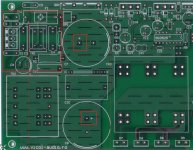
this is pcb post at first page (this thread).
4 +4 turns I think are good ( produces 23-24V on regulators (+ / -15V)
This is our first version pcb and pcb was completely redesigned.
Mark,
2 x 4 turns is OK for aux.
Regards,
Tibi
I would like to know if the specific problem mentioned have been properly dealt with, please
About better and more secure solder pads on supply caps, right ?
Man, I once had a 20mm spark jump, just because of a loose screw on a supply cap
About better and more secure solder pads on supply caps, right ?
Man, I once had a 20mm spark jump, just because of a loose screw on a supply cap
Hi Tinitus,
do not know the complete schematic and not even the latest release of PCBs.
But first pcb public in this thread, puts people at risk.
I would like to know more too.
invite TVICOL, a public full documentation, (if this is public)
do not know the complete schematic and not even the latest release of PCBs.
But first pcb public in this thread, puts people at risk.
I would like to know more too.
invite TVICOL, a public full documentation, (if this is public)
@AP2, you are refering to the first version of the board. People here are building V2. You can see it on the photos on page 7 or 8 of this thread.
@Tibi,
please don't do it 😡. I'm asking for a specification of all windings (including pins and turns) and you give only the last one - without pins.
As I mentioned previously, the photos on page 8 do not clarify anything since even the first photo (1-st part primary) shows the winding between 6 and 11 pins (if I count them correctly). It's completely different on the schematic. Other photos are too dark to clearly identify the pins. I wanted to order the transformer today but I cannot do it without proper specification.
The simplest way to provide such a specification is to create it in this form:
pin x, y -> pin z, w - primary winding (part 1) - N turns,
and so on ...
Is it a problem?
Another question: is the +/-15V widing also done with a litz wire?
Mark
n two weeks you've implemented your knowledge ... good!
I can see the schematic last rev. ?
PCB on first thread post was designed two years ago.
Full documentation including schematic will be available to public. Anyhow more info can be seen on vicol-audio.ro site.
On other hand I see that you develop power supplies http://www.audiopower.it/
You may wish to share with diy community your knowledge and share schematic and documentation. 🙂
Tibi
Thanks Markus2006,
I think that a project of PSUs, should be public only when it is finished and well tested.
I'm curious to see the final schematic, (I missed a few episodes)🙂
I think that a project of PSUs, should be public only when it is finished and well tested.
I'm curious to see the final schematic, (I missed a few episodes)🙂
Mark,
I'll make some more detailed pictures and also point on a drawing how the primary and secondary are connected.
Yes, you can use litzwire for secondary as well.
Regards,
Tibi
I'll make some more detailed pictures and also point on a drawing how the primary and secondary are connected.
Yes, you can use litzwire for secondary as well.
Regards,
Tibi
Thanks Markus2006,
I think that a project of PSUs, should be public only when it is finished and well tested.
I'm curious to see the final schematic, (I missed a few episodes)🙂
Why I expect that you are copying ?
Your SMPS designs looks to something I have fixed very long time ago.
yes, my job is to develop many things, but I have no commercial interest, I am in R & D.
in another thread I talked about my product (simlpe PSU), just to understand that it is not easy to build a PSU for audio amplifier. building is simple to turn lamps.🙂
in another thread I talked about my product (simlpe PSU), just to understand that it is not easy to build a PSU for audio amplifier. building is simple to turn lamps.🙂
Nick
Why I feel that I know you?
Have you changed your Nick name?
UK AMPS
yes, my job is to develop many things, but I have no commercial interest, I am in R & D.
in another thread I talked about my product (simlpe PSU), just to understand that it is not easy to build a PSU for audio amplifier. building is simple to turn lamps.🙂
Why I feel that I know you?
Have you changed your Nick name?
UK AMPS
Thanks,
Photos will be OK, but why can't you just present the information in a simple table here? Like this:
1st half primary, pin x -> pin y, 12 turns,
1st half secondary (1), pin x -> pin y, 9 turns,
2nd half secondary (1), pin x -> pin y, 9 turns,
2nd half primary, pin x -> pin y, 12 turns,
1st half secondary (2), pin x -> pin y, 4 turns,
2nd half secondary (2), pin x -> pin y, 4 turns.
All you have to do is to put proper numbers instead of x and y variables. Is it a problem or these pins are secret? 😀 . I need this information today. Email me if this is a secret.
Mark
A
Markus2006
I can Agree with you, that Vicol must supply such details in a paper, that INDICATES exact winding process, wire size, winding order, Each winding = how many volts (so you can get the voltage you need).
There are lot of details missing, specialy for new SMPS developers.
I agree
Markus2006
I can Agree with you, that Vicol must supply such details in a paper, that INDICATES exact winding process, wire size, winding order, Each winding = how many volts (so you can get the voltage you need).
There are lot of details missing, specialy for new SMPS developers.
I agree
- Home
- Amplifiers
- Power Supplies
- ±50V SMPS for Quasar Amps (& others)