@Mark
C46, 47, 52, 53 (1000uF/25V) are used both on SS and Tube version. I guess you're right regarding C52 and jumpers from Vaux module, since for the caps recommended in BOM they are at limit. It seems my 3D outlook wasn't so good. 🙁
For 15v choice, you don't need jumpers and either R21 and R23.
LT1086, R25 & R26 are doing the job.
Your remarks regarding Jp4 are correct.
Jp3 & 4 are used when MBR3045 is used as D13.
Also, Jp4 is used when Vaux = +V/0v/-V , and not used when 2 independent Vaux are necessary (+V and 0v).
Yes, R33 is 15k. There is no voltage divider, if you refer to an image posted on romanian forum (by florinccc); it's just a convenient replacement for the resistor (2 res in series), since the user didn't have 15k.
Regards, Geani
Thanks Alex for the photos. I see now that I soldered LT1086 reversed (also some people on the Romanian forum did the same) 🙁. I see also that you solve the problem with jumpers by soldering them on the oposite side of the board. This will cause that you will be not able to attach the board to a heatsink (if this is needed). I think that I will just remove them since they are not needed for =/-15V version.
I'm also looking for some heatsinks. I've got one for the diodes and another one for 7815. I wonder whether it is recommended to attach Q1, 2 and D13 to the same heatsink (even if they are isolated). The transistors are on the primary side while D13 is on the secondary side.
Mark
I'm also looking for some heatsinks. I've got one for the diodes and another one for 7815. I wonder whether it is recommended to attach Q1, 2 and D13 to the same heatsink (even if they are isolated). The transistors are on the primary side while D13 is on the secondary side.
Mark
So I guess they shouldn't be marked green in BOM. This is one of the reasons why I asked Tibi several times about the meaning of green color in BOM. Now I understand that green is for "tube" version but several components are marked incorrectly.C46, 47, 52, 53 (1000uF/25V) are used both on SS and Tube version. I guess you're right regarding C52 and jumpers from Vaux module, since for the caps recommended in BOM they are at limit. It seems my 3D outlook wasn't so good. 🙁
Just to recap: for SS version (+/-15V) both Jp3 and Jp4 should be shorted, right?Your remarks regarding Jp4 are correct.
Jp3 & 4 are used when MBR3045 is used as D13.
Also, Jp4 is used when Vaux = +V/0v/-V , and not used when 2 independent Vaux are necessary (+V and 0v).
It seems to me that R33 is not listed in BOM.Yes, R33 is 15k. There is no voltage divider, if you refer to an image posted on romanian forum (by florinccc); it's just a convenient replacement for the resistor (2 res in series), since the user didn't have 15k.
Mark
I adjusted the BOM for more precisely informations. Instead of colours you'll find the specific remarks. And yes, R33 was omited by my mistake.
If your Vaux is +V/0V/-V just short Jp4.
I'll draw some schematic to reveal the options of the board, regarding Vaux.
Regards, Geani
If your Vaux is +V/0V/-V just short Jp4.
I'll draw some schematic to reveal the options of the board, regarding Vaux.
Regards, Geani
Hi,
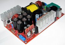
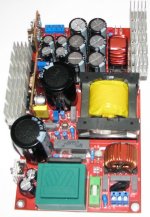
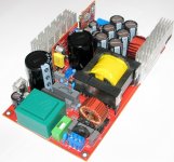
....my SMPS board is almost ready just missing some SMD resistors and can do some tests.
pictures of the SMPS
Regards Alex .
Can you tell your transformer winding details?
Specially, wire used, strands. etc...
Friend Markus2006
Its good to keep asking, SMPS are not a joke, so be carefull and good luck
I advice you to test the power supply with a transformer, 160V AC, 4 Amp. as a start up.
If things went OK, you can proceed to the 220VAC test.
Take EXTRA care with OFFLINE SMPS, they might be a kiss of death!
Fox
This is a fact 🙂
I need the same. Soon I'll be winding the transformer/or I will order it from a company that make such transformers on a daily basis. I haven't seen much info about it. I've seen only 2-3 photos, that it.Can you tell your transformer winding details?
Specially, wire used, strands. etc...
Could you provide the description in a format like in this document from Power Integrations (chapter 7): http://www.powerint.com/sites/default/files/PDFFiles/der20.pdf ?
With such a precise description one cannot do it incorrectly.
Now I realized that some clarifications concerning double/tripple diode is still needed 🙂. Do I think correctly taht you use either two BYV79 diodes, or one (double) MBR4045 diode? And in MBR4045 case Jumper3 is shorted? Some clarifications here would be nice.
Maybe last question: can 1000uF/200V be used instead of 1200uF/200V? I cannot buy the latter one (unless I'll buy them in the States but this is expensive). Will it deteriorate power supply parameters?
Mark
Turns
PRIMARY TURNS is 24 Turns
1/2 Primary (12 Turns)
All Secondary (32 Turns _Center Tap_) for +-95VDC
1/2 Primary (12 Turns)
Primary 2MM LITZ wire (Thanks VICOL)
Secondary 1.65MM, 4x0.4mm
ALL IN SAME direction, Isolation paper (you can use any isolation craft paper, or somthing close, two layers AT LEAST) or mylar TAPE_
That is my configration, TAKING in mind the value for the ZENER diode.
so I dont think you need that high voltage, you can lower the secondary TURNS.
This supply will work, if you spend some time checking carefully.
Good design,
Fox
Hmm, this is very confusing. Especially the secondary winding. Can you explain what you mean by:
Here is what I've got from Tibi:
"For sec winding use two separate sections with 3 turns each (with litzwire)."
So with this specification I still cannot make the trafo. Please explain.
Mark
Is it 32+32 or 16+16? We are building here +/-50V SMPS and you specify details for +/-95V. Is it a typing mistake or you are building different version of the power supply?All Secondary (32 Turns _Center Tap_) for +-95VDC
Do you mean 4 wires 0.4mm? I've got information that secondary should be wired also with litz wire and completely different number of turns.Secondary 1.65MM, 4x0.4mm
Here is what I've got from Tibi:
"For sec winding use two separate sections with 3 turns each (with litzwire)."
So with this specification I still cannot make the trafo. Please explain.
Mark
I haven't checked the BOM yet but I noticed that TR5 choke specified as #163-6292 from Farnell is not correct. I ordered it and I found out that it is much smaller than expected (should be 25x15 mm). It looks like a bug in Farnell catalogue (or they sent me completely different choke). Have you ordered it from Farnell or from somewhere else?@mark
I hope this BOM will answer your questions
Mark
Transformer
Markus
Please note that transformer is done as per MY specifications. ONLY
its for your REFRENCE also, Dont STICK with that!
Markus
Please note that transformer is done as per MY specifications. ONLY
its for your REFRENCE also, Dont STICK with that!
I haven't checked the BOM yet but I noticed that TR5 choke specified as #163-6292 from Farnell is not correct. I ordered it and I found out that it is much smaller than expected (should be 25x15 mm). It looks like a bug in Farnell catalogue (or they sent me completely different choke). Have you ordered it from Farnell or from somewhere else?
Mark
Markus,
Things are much easier than you think, You can get any Ferrite core from ANY computer SMPS (for you to save time, and complete this) and wind a 2MM wires on that, I think you need 2.5MH (ask Vicol )
It must work, without buying the orginal part.
what is your progress in that SMPS?
Thanks, good idea but I need information of winding:Things are much easier than you think, You can get any Ferrite core from ANY computer SMPS (for you to save time, and complete this) and wind a 2MM wires on that
I think it's rather 2x1mH. And the number of turns most probably depends on the core used. I may just order it but first I need precise information on the output transformer (just to order both components together). Alternatively, I could make the trafo on my own but at the moment I only know that the secondary is somewhere between 3 and 32 turns. I need more precise information 🙂.microsim444 said:, I think you need 2.5MH (ask Vicol )
It's about in 80% assembled. I don't have output transformer, output choke, SG3525-SMD, 1200uf/200V and few other capacitors. I would post a picture but I don't want to post pictures of only partly assembled supply - this may be confusing to other users.microsim444 said:what is your progress in that SMPS?
Did you complete your power supply? Which power amp are you going to use with +/-95V SMPS?
Mark
Assembly
MY SMPS will be ready in a week, since I dont have all parts, but I have the ETD49, output chockes,
I also wait my 100MHz scope to arrive, since I want to learn from this SMPS also.
Vicol should help you more than I can, since its HIS design.
But keep asking! be carefull when testing
I will power an old class AB amplifier with this SMPS.
But we all still need a report about 800~1000W continous load
Last edited:
At page 8, starting with post 77, you’ll find the necessary information to make your trafo.Markus2006 said:Is it 32+32 or 16+16? We are building here +/-50V SMPS and you specify details for +/-95V. Is it a typing mistake or you are building different version of the power supply?
As for the chokes, why don’t you use the simple way and look in the BOM at the prededing page? There you’ll find the Farnell codes for specific components. I mean 1MH 12A and 3.3MH 6A.
Regards, Geani
Last edited:
Hi,
24 turns on primary side and 16+16 for sec, produces (at 230Vac) vout of
+/-106V. at 99%PWM.
This PSU working with 99% PWM?
Mosfet is quiet,regulations....where is it?
24 turns on primary side and 16+16 for sec, produces (at 230Vac) vout of
+/-106V. at 99%PWM.
This PSU working with 99% PWM?
Mosfet is quiet,regulations....where is it?
Thanks, I somehow overlooked these photos.At page 8, starting with post 77, you’ll find the necessary information to make your trafo.
So finally it's for +/-51V:
1 part primary: 12 turns
secondary: 9+9 turns
2 part primary: 12 turns.
In all cases it's litz wire.
In the BOM rev2 there was not code for TR5. And the lead spacing was listed as 10x12mm (which is not correct - it should be 15x25). I've got from Tibi code 163-6292 (Farnell), which is also not correct. I ordered it and found out that it's too small for the board. Now you say it's 163-6298 - this is most probably the correct one. But since the delivery fee from Farnell is high, I'll most probably order it locally.
Mark
Sorry but I still have to ask you for the specification of the output transformer 😡. It's because I wanted to order it from a local company and I found out that I'm not able to provide a clear specification. This is due to the fact that the photos provided on page 7 completely do not match the schematic. Additionally, they completely neglect the fact of +/-15V windings (secondary #2).
For example, if you look at the schematic and the photos, you will find that the schematic shows the primary as single winding between pins 5 and 6 (shorted) and pins 9 and 10 (also shorted), while the photos show first part of the primary windings between pins 6 and 11. Other photos are too dark to clearly identify the pins. Can't you just provide the description of the transformer as it is done by professional companies e.g. Power Integrations in this sample document: http://www.powerint.com/sites/defaul...iles/der20.pdf (in chapter 7)?
Alternatively you could just provide a list of windings in the form:
pin x, y -> pin z, w - primary winding (part 1) - N turns,
and so on ...
You should provide 6 such lines: 2 for the primary (2 parts), 2 for the secondary (+/-51V) and 2 for the second secondary (+/-15V).
I could also analyse the board but I this that the author of the project will do it much faster. Please note that the second secondary windings were never specified in this topic. Is it 2x2 turns?
Is it really so difficult to provide such a simple information 😕?
Mark
- Home
- Amplifiers
- Power Supplies
- ±50V SMPS for Quasar Amps (& others)