Thanks Alex,
I realized that a long time ago. I was just wondering why it was so difficult to provide such a simple information. You must admit that answers regarding MBR3045 were very confusing or even misleading (TO-3 package). Now everything is clear.
Mark
I realized that a long time ago. I was just wondering why it was so difficult to provide such a simple information. You must admit that answers regarding MBR3045 were very confusing or even misleading (TO-3 package). Now everything is clear.
Mark
This is my first post here so i say hello to all.
I learn a lot of things by reading from DiyAudio but, since now, i did not feel that I have something to say and the fact that I am not a native speaker of english stop me from saying anything.
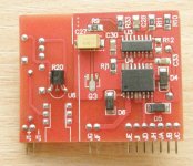
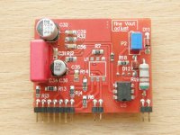
I build this SMPS, see pictures:
-the construction:
http://i45.tinypic.com/200y6pk.jpg[/IMG] BIG1
http://i45.tinypic.com/ws07pd.jpg[/IMG] BIG2
http://i50.tinypic.com/339kqci.jpg[/IMG] small1
http://i46.tinypic.com/f2j66t.jpg[/IMG] small2
One modification at tl431, i use 2 zenners instead
http://i49.tinypic.com/zk27gz.jpg[/IMG] detalii zenere
Trafo detail:
http://i49.tinypic.com/29eqa6t.jpg[/IMG] traf sec3si4
Testing:
http://i50.tinypic.com/33kwu2o.jpg[/IMG]
In load, one at 30W, one at 180W, one at 500W:
http://i46.tinypic.com/nmdfzc.jpg[/IMG] infunctune cu bec
http://i39.tinypic.com/2hs2737.jpg[/IMG] 180W
http://i42.tinypic.com/15d008w.jpg[/IMG] 500w
And one whith the tool i use for solder SMD 🙂
http://i43.tinypic.com/33lpet0.jpg[/IMG] letconul
I learn a lot of things by reading from DiyAudio but, since now, i did not feel that I have something to say and the fact that I am not a native speaker of english stop me from saying anything.
I build this SMPS, see pictures:
-the construction:
http://i45.tinypic.com/200y6pk.jpg[/IMG] BIG1
http://i45.tinypic.com/ws07pd.jpg[/IMG] BIG2
http://i50.tinypic.com/339kqci.jpg[/IMG] small1
http://i46.tinypic.com/f2j66t.jpg[/IMG] small2
One modification at tl431, i use 2 zenners instead
http://i49.tinypic.com/zk27gz.jpg[/IMG] detalii zenere
Trafo detail:
http://i49.tinypic.com/29eqa6t.jpg[/IMG] traf sec3si4
Testing:
http://i50.tinypic.com/33kwu2o.jpg[/IMG]
In load, one at 30W, one at 180W, one at 500W:
http://i46.tinypic.com/nmdfzc.jpg[/IMG] infunctune cu bec
http://i39.tinypic.com/2hs2737.jpg[/IMG] 180W
http://i42.tinypic.com/15d008w.jpg[/IMG] 500w
And one whith the tool i use for solder SMD 🙂
http://i43.tinypic.com/33lpet0.jpg[/IMG] letconul
Making the trafo for a 2 x 51V output.
Use Litzwire 120 x 0.1
5. wind second primary part, 12 turns.
You may add an copper shielding. I didn't had copper foil so ...
The trafo is ready to be mounted.
Regards,
Tibi
hello tvicol,
can i find litz whire in Romania, or somewhere near Romania?
Regards,
This is my first post here so i say hello to all.
I learn a lot of things by reading from DiyAudio but, since now, i did not feel that I have something to say and the fact that I am not a native speaker of english stop me from saying anything.
I build this SMPS, see pictures:
-the construction:
http://i45.tinypic.com/200y6pk.jpg BIG1
http://i45.tinypic.com/ws07pd.jpg BIG2
http://i50.tinypic.com/339kqci.jpg small1
http://i46.tinypic.com/f2j66t.jpg small2
One modification at tl431, i use 2 zenners instead
http://i49.tinypic.com/zk27gz.jpg detalii zenere
Trafo detail:
http://i49.tinypic.com/29eqa6t.jpg traf sec3si4
Testing:
http://i50.tinypic.com/33kwu2o.jpg%5B/IMG%5D
In load, one at 30W, one at 180W, one at 500W:
http://i46.tinypic.com/nmdfzc.jpg infunctune cu bec
http://i39.tinypic.com/2hs2737.jpg 180W
http://i42.tinypic.com/15d008w.jpg 500w
And one whith the tool i use for solder SMD 🙂
http://i43.tinypic.com/33lpet0.jpg letconul
Fixed links...
BTW isn't this a 1kw supply? so why does it already have 5v drop?
Last edited:
hello tvicol,
can i find litz whire in Romania, or somewhere near Romania?
Regards,
Hello savu,
Try AFERO - Ferrites & Accessories / Inductive Components - Romania - Epcos, Cosmo, TDK representative, they are elektrisola distributor in Romania.
Regards,
Tibi
Fixed links...
BTW isn't this a 1kw supply? so why does it already have 5v drop?
Yes, the smps will handle 1KW, but you need ventilation as some components - output diodes, trafo - will get hot.
I order to get a lower drop and to run with choppers cold, the trafo must be made very tight and no buzz sound must be heard at any load.
Regards,
Tibi
My SMPS ver.2:
Pictures:
1. In construction:
1111 Pictures, 1111 Images, 1111 Photos, 1111 Videos - Image - TinyPic - Servizio di hosting d'immagini, condivisione immagini & hosting di video gratuito
ghfgjhvcd Pictures, ghfgjhvcd Images, ghfgjhvcd Photos, ghfgjhvcd Videos - Image - TinyPic - Servizio di hosting d'immagini, condivisione immagini & hosting di video gratuito
gdsgsdgsd Pictures, gdsgsdgsd Images, gdsgsdgsd Photos, gdsgsdgsd Videos - Image - TinyPic - Servizio di hosting d'immagini, condivisione immagini & hosting di video gratuito
vbcbcx Pictures, vbcbcx Images, vbcbcx Photos, vbcbcx Videos - Image - TinyPic - Servizio di hosting d'immagini, condivisione immagini & hosting di video gratuito
2. Winding transformer:
- First layer (first half of primary): 3 Pictures, 3 Images, 3 Photos, 3 Videos - Image - TinyPic - Servizio di hosting d'immagini, condivisione immagini & hosting di video gratuito
-one layer of insulation : 22222 Pictures, 22222 Images, 22222 Photos, 22222 Videos - Image - TinyPic - Servizio di hosting d'immagini, condivisione immagini & hosting di video gratuito
cdgdfg Pictures, cdgdfg Images, cdgdfg Photos, cdgdfg Videos - Image - TinyPic - Servizio di hosting d'immagini, condivisione immagini & hosting di video gratuito
-secondary winding hjhyuuy Pictures, hjhyuuy Images, hjhyuuy Photos, hjhyuuy Videos - Image - TinyPic - Servizio di hosting d'immagini, condivisione immagini & hosting di video gratuito
fgfhgfjhfgh Pictures, fgfhgfjhfgh Images, fgfhgfjhfgh Photos, fgfhgfjhfgh Videos - Image - TinyPic - Servizio di hosting d'immagini, condivisione immagini & hosting di video gratuito
-another layer of insulation and next half of primary: dfsdfsdgf Pictures, dfsdfsdgf Images, dfsdfsdgf Photos, dfsdfsdgf Videos - Image - TinyPic - Servizio di hosting d'immagini, condivisione immagini & hosting di video gratuito
-mounted transformer: dfgdfgsdfgsd Pictures, dfgdfgsdfgsd Images, dfgdfgsdfgsd Photos, dfgdfgsdfgsd Videos - Image - TinyPic - Servizio di hosting d'immagini, condivisione immagini & hosting di video gratuito
Here is the signal from the outputs ir : sfs Pictures, sfs Images, sfs Photos, sfs Videos - Image - TinyPic - Servizio di hosting d'immagini, condivisione immagini & hosting di video gratuito
3. Source in operation:
- with small load (2 bulbs 100w): fsafasdfsa Pictures, fsafasdfsa Images, fsafasdfsa Photos, fsafasdfsa Videos - Image - TinyPic - Servizio di hosting d'immagini, condivisione immagini & hosting di video gratuito
- with high load (2 serial resistance of 4.7 ohms and a light bulb in parallel), we obtained an output of about 1100 watts : juyiu786 Pictures, juyiu786 Images, juyiu786 Photos, juyiu786 Videos - Image - TinyPic - Servizio di hosting d'immagini, condivisione immagini & hosting di video gratuito
It for a short time because transistors were mounted on heatsink. Follows mounting tension auxiliary module for a rigorous test.
Not a good speaker of English, so excuse my mistakes 😀
My SMPS ver.2:
Pictures:
1. In construction:
1
2
3
4
2. Winding transformer:
- First layer (first half of primary):
5
-one layer of insulation :
6
7
-secondary winding
8
9
-another layer of insulation and next half of primary: 10
-mounted transformer: 11
Here is the signal from the outputs ir :
12
3. Source in operation:
- with small load (2 bulbs 100w):
13
- with high load (2 serial resistance of 4.7 ohms and a light bulb in parallel), we obtained an output of about 1100 watts : 14
It for a short time because transistors were mounted on heatsink. Follows mounting tension auxiliary module for a rigorous test.
Not a good speaker of English, so excuse my mistakes 😀
I had some time to work on the SMPS. It works but I have problems with voltage adjustment. There are two problems:
1. TL431 - incorrect resistors values,
2. error amp in SG3525 is not working as expected (this may be related to R12 change).
Ad 1. Maximum voltage for TL431 is 37V. It is set by resistors divider (R18, P2 and R20). With the values designed (750R, 5k nad 10k) calculated range of voltage change is from 36V to 52V which is definitely wrong. I decreased R20 to 3k3 and now I can change the voltage on TL431 from 15V to 30V. Also the current through TL431 (and 4N25) seems way to high (Zener diodes get very hot). I think that R19 should be increased.
Ad 2. There were some changes related to R12. I don't think that the change is correct. The error amp in SG3525 compares voltage from voltage divider (R10 and R11) with voltage from transoptor. If you disconnect R12 from ground and put it in series with IN-, the IN- is "floating" and you cannot adjust the voltage (there is no voltage difference).
So as a result I get 2x58V but I cannot adjust the voltage.
Any advise?
Mark
Last edited:
1. The role of TL431 is to work as a CCS and maintain a constant current through feed-back Zeners.
By adjusting P2 you will change current through zeners, but output voltage will vary in a small range.
By decreasing R20 obviously you are moving the CCS to the high current region over or near -Izmax.
2. Error amp in SG3525 is an inverted operational and this is one main reason why R12 was changed.
3. This is normal, as you are running now CCS at higher current, Zener´s will get hot.
I explained above why R12 was changed.
To get another voltage output you need to replace zenners.
Example. For +/- 60V output, use two 61V zeners or three 39V zeners.
Regards,
Tibi
OK, I made it running but I'm still not happy (especially with TL431). With compnent values on the schematic (Zeners 15V and 51V) I got only 2x32V on the outputs. I found out that if I add another Zener diodes in series, I get expected output voltages. I get 2x48V with 15+20+10+51 Zeners. I put 2 resistors on the outputs (8 Ohms/200W) and the output voltages were almost unchanged. The D7-D10 diodes and the switching transistors are getting slightly warm (but not hot). So everything seems to be fine except TL431. There is 0V between anode and cathode. I 'd rather expect that it works like a variable Zener diode (exactly as it is described in the datasheet). The IC is OK (I replaced it with a new one), it is not shorted and of course I'm not able to adjust the output voltage. I didn't test it but I think that if I short U6 (anode and cathode) with a wire, I get the same results - so it seems that U6 is not working at all.
Tibi, can you measure voltages on D12, D11, U6 and R19 in your SMPS? And what are the output voltages?
Mark
Tibi, can you measure voltages on D12, D11, U6 and R19 in your SMPS? And what are the output voltages?
Mark
Markus,
The SMPS will give you exact the sum of zeners values from feedback network.
So you have 15+20+10+51=96 wich is exact what you get: 2 x 48V at the output.
Output will stay unchanged even with very high loads, over 800W will see a sighly decrease of 0,5 -1V.
TL431 was designed to work as a constant current source, please don´t expect to work in any other way.
Regards,
Tibi
Tibi, can you still measure the voltages that I asked for in my previous post? Is 0V on TL431 a correct value (from anode to cathode)?
Mark
Mark
Mark,
On mine TL431 I have 11V.
Please check if your TL is correct mounted and not broken, you should not get 0V across him.
Regards,
Tibi
On mine TL431 I have 11V.
Please check if your TL is correct mounted and not broken, you should not get 0V across him.
Regards,
Tibi
Tibi, what about other voltages (R19, D11, D12, 4N25 - diode)?
My SMPS is working (after some modifications) but I get very noisy signal on the output. Can you post a photo of the voltage on the output (with sensivity e.g. 0.2V/div)? Mine does not look nice.
Why TL431 is not frequency compensated? It wasn't needed?
Mark
My SMPS is working (after some modifications) but I get very noisy signal on the output. Can you post a photo of the voltage on the output (with sensivity e.g. 0.2V/div)? Mine does not look nice.
Why TL431 is not frequency compensated? It wasn't needed?
Mark
Please accept my apology in advance. I am trying make heads or tails of this long thread, and I am apologizing to those that know more than I do for the intrusion. BUT I have a few questions, and I hope to clarify for myself and maybe others some of the basics of this power supply.
First, is this a DIY project or a commercial one.
Is there a current schematic available?
Can I purchase up to date pcb for the project?
IF I can where and at what cost?
What output currents and voltage is this SMPS capable of?
Can I purchase parts?
What would the whole “KIT” cost if there was one?
Thanks for your thoughts if you share them….
Tibi, what about other voltages (R19, D11, D12, 4N25 - diode)?
My SMPS is working (after some modifications) but I get very noisy signal on the output. Can you post a photo of the voltage on the output (with sensivity e.g. 0.2V/div)? Mine does not look nice.
Why TL431 is not frequency compensated? It wasn't needed?
Mark
Do you want to measure voltage across zener diodes ? 🙄
Glad you got SMPS working !

I have posted some measurements in this thread http://www.diyaudio.com/forums/power-supplies/149702-50v-smps-quasar-amps-others-9.html#post2038240 .
Do you think that compensating TL431 will improve SMPS feedback ?
Regards,
Tibi
- Home
- Amplifiers
- Power Supplies
- ±50V SMPS for Quasar Amps (& others)