Draga tIBI si jeg-kraxi
naw can see i not only have bullished and have more pepols problem with the source and the reason is simple. you sell the "bear skin from the woods" and this hapent. maybe is not shame to recognize that you have zero practic with sources and learn with peoples money. or maybe not learn noting. from last time i tell you befor one month i learn probabil more like you now about sources and i want only to tellyou i not ned the source pcb from you anymore becoz i start to make my source and doing good now. in romanian forum and mail you speak to superior and think evetybody is idiot when ask you to help or how to repare mistakes. naw yu not answer anytime for me i send many mail at office@vicol-audio.ro sales@vicol-audio.ro pcbdesign@vicol-audio.ro and not have time to reply.
before first time you say the source can give 18-20A at +-50 to +-60V simple matematic tell me that this is 1800W to 2400W. ofcourse must say this to make pepols belive and send money for grup-gay. after you corect and say 10A only. 2400W is more then 20A the curent in transistors and pek is 30A. you use IRFP460 and half bridge ? and peoples say the source make BUM!!!
you NEVER make real test with someting to see the power what you say that have. you sell chinezian source 🙂) 10000000000W PMPO
maybe the light in the picture have the power what you say.
i sped time and read the lections from ANDREI GRADU who is a genius in sources in elforum and teach you every time how to do this do that. i read boks and i make my source in next weks.
after almost half year when you say the source you make the pcb and more then 3-4 months when you have the pcb some pepols who pay money not get the pcb, only in the last weks some sent for them. tis becoz is not version 2 is 3 or maybe 4. you need time to corect one mistake and make another 5 and send the pcb to make together with quasar, volume controler and other group-tzapa you make. if you so good design why need 13 version for quasar ? i never see the results there only stimulation in ltspice. my ticher at schol say the stimulation can be very fake from reality if you not good to make real model for transistors.
who is geani ? who is JEG-kraxi ? who is andiy ? who is andrei popescu ? who are some other pepols who are your suporters and hide after the nickname ? why he hide ? why he lie ?
he say not sent the pcb becoz not have time and some very funy explanations like political problems in romania - alegerile he change the house, he have sick, he have no components for pcb.
you like to say to everibody the source not working because he use chip capacitors and bad quality only superexpensive working maybe becoz they canot get and get some time and make new version, take money again from everibody, etc. you sey the transformer not working with normal wire only with the expensive one whay you sell. you had somebody asking for 10-20m this wire for other thing and canot buy so litle and ned to find motive to buy 400m. 🙂) and with this wire you make the transformer more bad than a chip computer chineze atx source transformer.
maybe you planing to open shop to sell expensive components for amplifiers which make the cost like an apartment in pipera and the sound like a trabant, but not the new version who come this year.
i want to go to your home to se the amplifier and source working becoz you say this many time who want to go to se can calling you to meet. after, if is real what you say and not real what i say i excuze to everibody for what i say now. if is not real, you must excuze and give money back to pepols who you lie all time.
microsim44 ????????????????
Take it easy friend.
I dont understand, What the hell is your problem with the VICOL SMPS?

Thanks guys,
This clarifies most of the problems. However, few are still unclear.
It seems that TEZ4/D/15V indicated in BOM is not correct. It has only single windings and the secondary winding is connected to pins 7 and 9. It should be rather connected to 6-7 and 9-10 if I remember correctly (I don't have the board here with me).
Ha, ha. And the picture you attached shows just the oposite 😀. I guess it just doesn't matter.
This brings me back to my remark #1 - remarks in Romanian on the schematic. I don't understand it. Are you saying that the diodes are exactly as indicated on the schematic or there should be some modification?
Regards,
Mark
Mark,
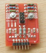
Tr3 can be 1+1; 1+2; 1+3; 2+1 ...... 3+3. Any combination, as long this can feet the board and is 110V/220V to 15-18V output.
We wanted to offer more flexibily, but seems that this produced more confusion.
However, please follow my previous advice and use what trafo make you comfortable: TEZ4/D/9-9 from TME is OK.
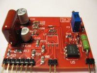
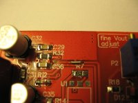
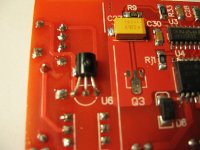
I have attached few more pictures. Hope this will help you and answer your questions.
Components marked with green are only for tubes version, or are present in both versions with different values.
D13A/B/C are exactly as in schematic. We just wanted to simplify and use a double diode, but again this generated confusion. :-~
Regards,
Tibi
Attachments

Last edited by a moderator:
Markus,
As I said, the board supports a lot of types of linear transformers. Previously I indicated a 2 primary windings transformer (110V+110V) which is not your case. Also, Jp1 & Jp2 help you to switch between 110v and 220v mains, FOR THE ABOVE type of transformer.
If you have TEZ4/D/15v, I guess it is not a problem to you to connect pin 6 to pin 7 and pin 9 to pin 10 on the board. 🙂
C38-43 (2200uF/63V) are indeed for SS version and alternatively C58-59 (470uF/400V) are for tube version?
Both types are present in the schematic just because this was the way to put them also on the pcb board.
Regards, Geani.
Last edited:
Beg
It seems that we are dealing with beginners in here.
VICOL, I dont see any problems with your SMPS, and thanks for the FREE litz wire you sent me. Professional PCB
Also you (FLORIN thing), I dont think you are able to assemble that supply. since VICOL Schematic supports too many options that you cannot recognize. 😀
Thanks
Thanks,C38-43 (2200uF/63V) are indeed for SS version and alternatively C58-59 (470uF/400V) are for tube version?
Both types are present in the schematic just because this was the way to put them also on the pcb board.
I wasn't asking why the capacitors are in the schematic 😀. I was asking why they are marked green in the BOM (which indicates tube version). I assume this is just a mistake.
Mark
Thanks,
I wasn't asking why the capacitors are in the schematic 😀. I was asking why they are marked green in the BOM (which indicates tube version). I assume this is just a mistake.
Mark
I'll try to revise the smps documentation for conceivable reading.
Only my spare time is a problem 🙂
For me it was clear from the very beginning that D13A and D13B is a dual diode and D13C is yet another diode. But in the new version of the schematic you put additional drawing of the dual diode exactly as it was before (without any changes) and put some comments in Romanian. The comments cannot be translated by language translators that I tried.D13A/B/C are exactly as in schematic. We just wanted to simplify and use a double diode, but again this generated confusion. :-~
So there was nothing confusing about the diodes until you tried to clarify it and put Romanian comments in the schematic. Hey guys, is it really so difficult to understand that people speaking different languages cannot unserstand some comment in Romanian? I don't believe that you don't see the problem 😕.
Thanks for the photos. I assume that additionally few pins of IR2110 should be disconnected from the ground.
Mark
Wouldn't it be much simpler to put the comments in English from the start? I tried babylon and some of the translations completely did not make any sense (they are technical and the translator cannot handle technical text).
At the moment everything is clear for me but I had to ask several questions. With English comments I wouldn't need to ask them 🙂.
Luka: I tried new version of Youtube service with Google translation (English->Polish) and I can tell you that the translations are completely wrong. Either they are funny or do not make sense at all. I assume that with other lagnuages it's the same, isn't it?
Mark
Last edited:
Mark,
I fully agree with you. Will translate all comments to English and send to you BOM & schematic.
Regards,
Tibi
I fully agree with you. Will translate all comments to English and send to you BOM & schematic.
Regards,
Tibi
Quote microsim666: "It seems that we are dealing with beginners
in here.
VICOL, I dont see any problems with your SMPS, and thanks for
the FREE litz wire you sent me. Professional PCB
Also you (FLORIN thing), I dont think you are able to assemble
that supply. since VICOL Schematic supports too many options
that you cannot recognize"
you spek rigt first time. here is beginers. have no shame to
recognize this, need have shame who tink very smart and sel to
pepols someting not working.
second time you have not ideea and i sure you not read what i
write.
YOU JUST SELL YOUR SOUL TO TEM FOR FEW METERS OF WIRE
what you cal profesional pcb ? what have more mistakes tan
components ?
i red you post and pepols jok

Florin
Would you kindly try and be more precise when posting
And leave out personal stuff please
Better "organised" posts would be easier to understand
Your english, and poorly organised posts, are very hard to read and understand, and the result may be misunderstandings
If we cant understand what you write, we may not be able to allow it
Sorry, but those are the rules
Smps
Florin
Experiance people, dont need 100% informations to assemble that SMPS, also I dont know VICOL in person NOR i stand with him for a few meters of litz wire.
Florin
Experiance people, dont need 100% informations to assemble that SMPS, also I dont know VICOL in person NOR i stand with him for a few meters of litz wire.
I'm not that experienced as Microsim so I'll keep on asking questions which arise when assembling the SMPS.
I have a problem with C46, 47, 52, 56 (1000uF/25V). They are marked as "tube" version in BOM. But I think that they are input and output capacitors for LT1086 in SS version, right? If yes, one of the capacitiors (C52) is exactly in the same place as jumpers on "C" board are. Of course I could remove these jumpers (since I'm building SS version and I think that the jumpers are not needed for +/-15V) but I'm worrying whether I made a mistake when assembling the supply. Can you post a photo of SS version assembled and show how the jumpers on "C" board fit in the same place as C52 capacitor?
Could you also explain Jp3 and Jp4 in SS version? I found a drawing that says that they should be connected only for "tube" version but I think that at least Jp4 should also be be connected for SS version (in order to get +/-15V).
EDIT: could you also explain R33? I cannot find it in BOM and on the schematic it's listed as 15k. On the other hand, on one of the photos posted it is replaced by two resitors (voltage divider).
Mark
Last edited:
Markus2006
Friend Markus2006
Its good to keep asking, SMPS are not a joke, so be carefull and good luck
I advice you to test the power supply with a transformer, 160V AC, 4 Amp. as a start up.
If things went OK, you can proceed to the 220VAC test.
Take EXTRA care with OFFLINE SMPS, they might be a kiss of death!
Fox
Thanks for the advice. Actually I was going to ask how to test safely the power supply. But at the moment still about 20% of components are missing. So first I need answers to my previous questions. Have you assembled the SMPS? If yes, you could answer at least to few of these questions. Otherwise, I'll wait for Tibi.
BTW, I managed to test the low voltage power supply. I bought 2x7.5V transformer. I get 24V on C21 (1000uF/25V). So it looks like 2x9V transformer would be slightly too much. On the schematic this capacitor is listed as 1000uF/35V - there are discrepancies between BOM and the schematic. I initially soldered 1000/25V capacitor but it looks like 1000uF/40V would be much better.
Mark
- Home
- Amplifiers
- Power Supplies
- ±50V SMPS for Quasar Amps (& others)