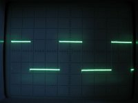
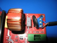
Due the fact we use a linear supply for PWM module, the MOSFET low side chopper drive, is very clean and not affected by load.
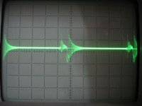
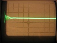
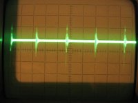
From left to right, first two pictures 2V / div. Last picture 5V / div.
Regards,
Tibi
From left to right, first two pictures 2V / div. Last picture 5V / div.
Regards,
Tibi
Attachments


Last edited by a moderator:
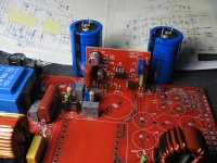
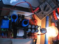
The SMPS is very stable and able to output almost any voltage from
+12V to +350V and +/- 12V to +/-175V.
An auxiliary variable supply was provided for tubes filament or any other application.
We are going to run a group buy at factory price with all SMD components ready mounted.
If there is any interest please let us know and I'll come back with estimated price.
Regards,
Tibi
simple and good. I have a question.
what is volts out with no load and 400W? (resistive load)
and if you've measured burst on amplifier?
what is volts out with no load and 400W? (resistive load)
and if you've measured burst on amplifier?
We are going to run a group buy at factory price with all SMD components ready mounted.
If there is any interest please let us know and I'll come back with estimated price.
i have subscrived to yor grup bay on romanian forum and i am ignored even today when i ask abot my pcbs. maybe here i have a chace to get the boards of ignored again.
wich version is this one bicose some forum membres told me the delay is bicose new pcb have so many mistakes and not working the tranzistos exploded and smoke. this problem is solved now or we have to cut traks and add wires like with the board before ?
simple and good. I have a question.
what is volts out with no load and 400W? (resistive load)
and if you've measured burst on amplifier?
For this SMPS total no load output is 102,1V
At 400W load output is 100.8V
I'll come back with more measurements.
Regards,
Tibi
wich version is this one bicose some forum membres told me the delay is bicose new pcb have so many mistakes and not working the tranzistos exploded and smoke. this problem is solved now or we have to cut traks and add wires like with the board before ?
This is version 2.
The group buy from elforum is still going on, as we are facing difficulties in sourcing some components from TME ( the stock is 0).
So, I don't know from who do you have this information, as I'm the single person who had components and built this version.
Due the fact we had few PCB mistakes on version 1, we have decided to improve layout and schematic and release version2.
Based on customers feed-back, we'll not stop here and improve this SMPS further.
Regards,
Tibi
Some suggestions:
Try to eliminate the small 50/60Hz transformer. A little auxiliary SMPS can provide isolated +/-12V and +5V while powering the primary side too, and allowing for remote turn on of the main SMPS without losing +/-12V (and/or +5V) during standby. I usually do that with Power Integrations Tinyswitch ICs and off-the-shelf transformers, part count is low, essentially using as much space as the 50/60Hz transformer, but it provides a wide input voltage range, current limiting and regulated outputs.
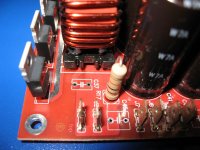
What you used in the transformer looks like paper and it's not a good idea because it becomes conductive with humidity. Try to get the usual polyester tape (Scotch 1298, 1318 or 1350).
The amount of RF ringing on the output is unacceptably high, it looks close to 200mV p-p, and even worse, it's probably common-mode interference. This ringing comes from a resonance that has to be damped, probably in the primary side when MOSFET d-s capacitance of the one turned off resonates with series inductance (including both TO-247 packages, PCB traces and supply capacitors to complete the loop).
Capacitance from output diodes can also resonate with trasnformer parasitics and output capacitor inductance. Damping this is quite easy: ferrite beads in series with the diodes (or just small ferrite rings on diode legs).
Otherwise, the overall layout looks good, and the will to reduce inductances and loop areas is appreciated 😉
Try to eliminate the small 50/60Hz transformer. A little auxiliary SMPS can provide isolated +/-12V and +5V while powering the primary side too, and allowing for remote turn on of the main SMPS without losing +/-12V (and/or +5V) during standby. I usually do that with Power Integrations Tinyswitch ICs and off-the-shelf transformers, part count is low, essentially using as much space as the 50/60Hz transformer, but it provides a wide input voltage range, current limiting and regulated outputs.
What you used in the transformer looks like paper and it's not a good idea because it becomes conductive with humidity. Try to get the usual polyester tape (Scotch 1298, 1318 or 1350).
The amount of RF ringing on the output is unacceptably high, it looks close to 200mV p-p, and even worse, it's probably common-mode interference. This ringing comes from a resonance that has to be damped, probably in the primary side when MOSFET d-s capacitance of the one turned off resonates with series inductance (including both TO-247 packages, PCB traces and supply capacitors to complete the loop).
Capacitance from output diodes can also resonate with trasnformer parasitics and output capacitor inductance. Damping this is quite easy: ferrite beads in series with the diodes (or just small ferrite rings on diode legs).
Otherwise, the overall layout looks good, and the will to reduce inductances and loop areas is appreciated 😉
Thank you Eva for your suggestions ! I really appreciate your advices.
We suggested to use waxed paper for winding isolations, but I'll make one trafo with your advice - polyester tape.
The presented SMPS dont have 10nF output filter capacitors mounted, due the fact we didn't sourced all components for this board yet.
There are missing input filter capacitors as well.
When mounted these will clean ven more the output.
Regards,
Tibi
Attachments
Other questions
decrease (at static) very little ... something I do not come back. you used to connect error amplifier the photodiode , this method has hysteresis and not linear, as big pulse (from current amp), force modulation PWM, which is why I asked you if you were measured under burst on amplifier ,rail voltage.
What is the percentage of PWM under 400W static load?
TO EVA:
Yes you say good insulation on the Transfer and ring ferroxube on diode
but link is insufficient for startup vcc. also +simple resistors not powered pwm+driver🙂. Takes pump circuit
Compliments for your preparation. (I read your other interventions on the forum)
thank you tibi for reply. i hope you can think of me here and send me pcb i need for the IPA400.
i send some email to you to address what you give office@vicol-audio.ro and sales@vicol-audio.ro and no reply. i spik to the man who make this source, you coleg andiy and he say to wait becoz this version with red color have the problems. i know you say the version before is no good, the one green but this red have some problems again. if this what you put photos here is more new i want to take 2 pcb. i send you email for this if you want to give me.
i send some email to you to address what you give office@vicol-audio.ro and sales@vicol-audio.ro and no reply. i spik to the man who make this source, you coleg andiy and he say to wait becoz this version with red color have the problems. i know you say the version before is no good, the one green but this red have some problems again. if this what you put photos here is more new i want to take 2 pcb. i send you email for this if you want to give me.

thank you tibi for reply. i hope you can think of me here and send me pcb i need for the IPA400.
i send some email to you to address what you give office@vicol-audio.ro and sales@vicol-audio.ro and no reply. i spik to the man who make this source, you coleg andiy and he say to wait becoz this version with red color have the problems. i know you say the version before is no good, the one green but this red have some problems again. if this what you put photos here is more new i want to take 2 pcb. i send you email for this if you want to give me.
Hello Florin,
We do not sell IPA400 boards. My advice is to get in touch with Vasile from elforum.ro
Well, this board - ver.2 - have no problems. The single issue is parts sourcing from TME. We may go to buy from farnel, but this will near triple the price...
I have boards available, so please mail to me.
Regards,
Tibi
Last edited by a moderator:
i dont know who are you and why you say this for me. i speak with andiy and he tell me that the source not working becoz have mistakes and make new pcb. he say to evreribody the components are hard to find to take some time to make new pcb when make the quad pcb together to not pay so much becoz this time pepols will not pay again. the pcb is expensiv for me and other romania peopls
Last edited:
Florin,
It's quite hard to decrypt your English. Please try to put words in order.
jkraxi and andiy are the same person. 🙂
Obvious there is a misunderstanding you may clear out with him in private.
Thanks for understanding.
Regards,
Tibi
It's quite hard to decrypt your English. Please try to put words in order.
jkraxi and andiy are the same person. 🙂
Obvious there is a misunderstanding you may clear out with him in private.
Thanks for understanding.
Regards,
Tibi
Last edited by a moderator:
...
Try to eliminate the small 50/60Hz transformer. A little auxiliary SMPS can provide isolated +/-12V and +5V while powering the primary side too, and allowing for remote turn on of the main SMPS without losing +/-12V (and/or +5V) during standby. I usually do that with Power Integrations Tinyswitch ICs and off-the-shelf transformers, part count is low, essentially using as much space as the 50/60Hz transformer, but it provides a wide input voltage range, current limiting and regulated outputs.
...
Try to get the usual polyester tape (Scotch 1298, 1318 or 1350).
...
Capacitance from output diodes can also resonate with transformer parasitics and output capacitor inductance. Damping this is quite easy: ferrite beads in series with the diodes (or just small ferrite rings on diode legs).
...
Thanks EVA for helping (educating) us - this is much appreciated.

Last edited:
- Home
- Amplifiers
- Power Supplies
- ±50V SMPS for Quasar Amps (& others)