Again, thank you.
At this point my configuration has the midrange and woofer -ve polarity, with the tweeter and mid woofer +ve polarity.
I will wait until the speakers are finished, and then make a change. I'll have the midrange and woofer +ve, and the tweeter and midwoofer -ve. I'll listen to music, and decide if one sounds better than the other.
Next question, and this one is weird.
First I will try to explain what happened.
The very very very first time I hooked up my woofer to the circuit, it produced a loud 'thud'. I was perplexed. I disconnected it, reconnected, and nothing. No thud.
I then hooked up my mid woofer, a gentler thud. Disconnect, reconnect, no thud.
The same for the midrange, and a mild pop from the tweeter.
This happened for all 8 drivers. But only once.
Being mathematically inclined, could you do me a favor?
Is my circuit a pseudo de-gauss'r?
Could it be a combination of air core inductors connected to feron 'cored' inductors?.
This is way beyond my abilities to figure out.
Hoping you can shed some light on this.
I'm not sure I quite grasped what you are describing there, but in general it is incorrect to run a filter without the drivers connected. It can produce a very reactive and difficult undamped load to the amplifier.
Since most amps have a DC offset around 0.1V anyway, thuds and crackles would not surprise until the amp gets a chance to settle. A feedback amplifier is very "aware" of the load's impedance. It's how they work.
Gotta dash now, but will try to get a sim of your filter going in the next few days. I'll be watching the phase and time alignment with interest. My intuition tells me it's going to be something about 18dB/octave and 9dB/octave. But time will tell.
Visaton Boxsim is very handy for adjusting time-alignment aka SEO or point of sound origin easily. You just dial it in as an offset in mm.
Thank you.
Quick note; the crossover was not connected to the amplifier when the thuds occurred. The crossover was free standing.
Quick note; the crossover was not connected to the amplifier when the thuds occurred. The crossover was free standing.
Oh, just a stray charge on a capacitor somewhere discharging, you would guess. Possibly even static electricity and sparks from an acrylic jumper of yours. 😀
Learning
Great communication fellas, this is the steps it takes to come up with a game changer in the world of audio. You guys are in hot pursuit of a crossover benchmark. I'm observing and taking notes.
Thanks for sharing your thoughts.
Great communication fellas, this is the steps it takes to come up with a game changer in the world of audio. You guys are in hot pursuit of a crossover benchmark. I'm observing and taking notes.
Thanks for sharing your thoughts.
Great communication fellas, this is the steps it takes to come up with a
game changer in the world of audio. You guys are in hot pursuit of a
crossover benchmark. I'm observing and taking notes.
Thanks for sharing your thoughts.
Hi,
Anything game changing requires rigour and there is none here.
Lots of handwaving nonsense that will not change anything.
rgds, sreten.
Sreten, you are just an old grump IMO! This is fun. 😀
Shallow filters are not usually my bag, but some people swear by them. Vandersteen and IIRC, didn't Dali make a series filter with 5 drivers that looked like a Quad ESL with cone drivers? Can't remember, can't find the circuit. KEF did some series filters too, years ago. The mid got an LC parallel shunt IIRC. The bass and tweeter got regular second order series. Again I can't dig it up right now, but it used the old elliptical B139 Concerto bass.
The simming is a bit of a nightmare so far, because Boxsim Optimiser keeps trying to ditch the upper mid and make a regular Fried style shallow three way.
But it's looking quite good so far. 8" plus 5" plus efficient dome tweeter. More of a regular three way though. Phase is saying alternate polarity for sure. Early days, I haven't tried very hard with time alignment or impedance correction. 😱
Attachments
Last edited:
Staying focused
That's right just keep the class in session. All we are concerned with is build great speakers. We can't please everyone, then again we're not trying to. This is for the fellas that won't to be better at DIY. Those that don't can visit a different forum. I think this is the best for those who truly want to learn! Let class continue.
That's right just keep the class in session. All we are concerned with is build great speakers. We can't please everyone, then again we're not trying to. This is for the fellas that won't to be better at DIY. Those that don't can visit a different forum. I think this is the best for those who truly want to learn! Let class continue.
system7 (Steve), you're too quick!!!!
I had hoped to type this post before your simulation.
This post will make no sense, and for that I apologize.
Story 1) when I was a much younger man, Quartz Lock turntables where the technology of the day. Many of us bought one.
Years later, most of us ditched these, and bought a simple belt drive TT.
Why?
We learned something.
A Quartz Lock turntable does not 'lock' onto 33.33 rpm.
A Quartz Lock is a type of differential engine.
This engine recognizes 33.32 rpm, and adds voltage, thereby increasing the TT speed.
Once the TT passes 33.33 rpm and hits 33.34 rpm, the engine recognizes there's too much speed. Reduces voltage.
In reality, the QL tt spends very little time at 33.33 rpm, and instead is constantly speeding up and slowing down.
Todays technology is orders of magnitude better, with 33.333334 rpm as the 'fast' point. Too Late!.
This differential engine lost us.
Story 2) cd's sound awful. I will conceit JVC XRCD's, and a few others figured it out. They're listenable. SACD is a lot better, with DSD being the equal of Analogue.
The original cd was produced with a type of differential engine algorithm.
This algorithm changed the waveform of sound. It did this so it could recognize the 'difference'.
Ideally the conversion back to analogue would have been the opposite algorithm, thereby restoring the original signal.
Unfortunately it couldn't and didn't.
This differential engine lost us.
The reason for this post?
Steve, thank you, thank you, thank you.
Crossover, and therefore speaker, simulations are a type of differential engine. The program is trying to 'correct' the drivers and crossover components so they will work together.
Your comment "simming is a bit of a nightmare" couldn't have made me happier.
Your differential engine can't recognize my crossover. My crossover is spinning at exactly 33.33333333333 rpm. I love it.
Midranges
Everywhere I have checked seems to be on back order for the Audax HM100Z0 with the phase plug. It would wind up costing me about $213.00 a pair to order from over seas with at least a 6 week wait. If I could find a deal on some ATC SM75/150 8ohm or something equal in a 4-5" paper cone. I might jump on them asap. Just saying!
Everywhere I have checked seems to be on back order for the Audax HM100Z0 with the phase plug. It would wind up costing me about $213.00 a pair to order from over seas with at least a 6 week wait. If I could find a deal on some ATC SM75/150 8ohm or something equal in a 4-5" paper cone. I might jump on them asap. Just saying!
Last edited:


It does seem that a good fullranger type mid could be good here. Low Le inductance always helps simple filters and Scanspeak do that well. Phase plugs and high Qms too, IMO. An SB acoustics ring radiator would be worth a punt too IMO. Theoretically better than soft domes, because the spitty middle is pinned, and approved by Steen Duelund too FWIW.
I'll digress with some more interesting ideas that are not in the mainstream while the back brain mulls the problem over here.
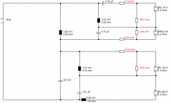
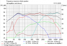
I mentioned the classic 3 way transfer function, which is 12dB/octave on bass and tweet and a 6dB slope on the mid in either direction. It can be either all pass or a phase network depending on polarity of the elements. s being jw, a complex variable. The three top terms are the three filters on a common denominator, here added up. They are, in effect LR2.
1 - 2s + s^2 / 1 + 2s + s^2
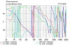
What the transient perfect speakers do is wire the bass and tweeter out of phase, then fill the alarming hole or null with the shallow mid. Interestingly the s terms each have a 90 degree phase change about them in the j term, which is the root of minus one. Or 180 degrees with s^2, you follow?
So the above filter has a 90 degree relation between each of the three driver's phase. This is not Linkwitz-Riley phase aligned at all.
This why Visaton Boxsim always messes them up, because its optimiser always tries for flat Frequency Response and flat phase. Which is not 90 degree butterworth at all. So you have to force it where you want it to go, and that can be done.
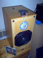
90 degrees phase...an odd concept. maybe it represent a physical right angle too. Speakers like my lash up below can sound good. Inspired by the wall mounting Roy Allison Model 4 to some extent.
I'll digress with some more interesting ideas that are not in the mainstream while the back brain mulls the problem over here.
I mentioned the classic 3 way transfer function, which is 12dB/octave on bass and tweet and a 6dB slope on the mid in either direction. It can be either all pass or a phase network depending on polarity of the elements. s being jw, a complex variable. The three top terms are the three filters on a common denominator, here added up. They are, in effect LR2.
1 - 2s + s^2 / 1 + 2s + s^2
What the transient perfect speakers do is wire the bass and tweeter out of phase, then fill the alarming hole or null with the shallow mid. Interestingly the s terms each have a 90 degree phase change about them in the j term, which is the root of minus one. Or 180 degrees with s^2, you follow?
So the above filter has a 90 degree relation between each of the three driver's phase. This is not Linkwitz-Riley phase aligned at all.
This why Visaton Boxsim always messes them up, because its optimiser always tries for flat Frequency Response and flat phase. Which is not 90 degree butterworth at all. So you have to force it where you want it to go, and that can be done.
90 degrees phase...an odd concept. maybe it represent a physical right angle too. Speakers like my lash up below can sound good. Inspired by the wall mounting Roy Allison Model 4 to some extent.
Attachments


Last edited:
sensitivity
Also all of my current transducers are 93db sensitivity. So for ease of crossover, something in this range would be great so that I don't have to pad the other transducers down. I was going to do a 3-way with dual AE TD12s woofers, AE TD6m mids, and the Audax TW025A20 tweeter. Would this be an excellent 3-way or is it a big benefit to do a 4-way taking in consideration i'm having a hard time finding an upper mid that is in the 91-93db range that is readily available and worth the extra cost. If the ATC SM75/150 8ohm 91db is truly the king of mids & worth the $600.00 each "NEW PRICE" then I can dig deep & spring for it if it will match up with my other transducers. Looking at the frequency it is really about the same range as the AE TD6m so I would still only have a 3-way speaker only now I would need to sell the AE TD6m and replace it with the atc sm75/150 and I don't if it is worth all the effort. What do you guys think?
Also all of my current transducers are 93db sensitivity. So for ease of crossover, something in this range would be great so that I don't have to pad the other transducers down. I was going to do a 3-way with dual AE TD12s woofers, AE TD6m mids, and the Audax TW025A20 tweeter. Would this be an excellent 3-way or is it a big benefit to do a 4-way taking in consideration i'm having a hard time finding an upper mid that is in the 91-93db range that is readily available and worth the extra cost. If the ATC SM75/150 8ohm 91db is truly the king of mids & worth the $600.00 each "NEW PRICE" then I can dig deep & spring for it if it will match up with my other transducers. Looking at the frequency it is really about the same range as the AE TD6m so I would still only have a 3-way speaker only now I would need to sell the AE TD6m and replace it with the atc sm75/150 and I don't if it is worth all the effort. What do you guys think?
Last edited:
Also all of my current transducers are 93db sensitivity. So for ease of crossover, something in this range would be great so that I don't have to pad the other transducers down. I was going to do a 3-way with dual AE TD12s woofers, AE TD6m mids, and the Audax TW025A20 tweeter. Would this be an excellent 3-way or is it a big benefit to do a 4-way taking in consideration i'm having a hard time finding an upper mid that is in the 91-93db range that is readily available and worth the extra cost. If the ATC SM75/150 8ohm 91db is truly the king of mids & worth the $600.00 each "NEW PRICE" then I can dig deep & spring for it if it will match up with my other transducers. Looking at the frequency it is really about the same range as the AE TD6m so I would still only have a 3-way speaker only now I would need to sell the AE TD6m and replace it with the atc sm75/150 and I don't if it is worth all the effort. What do you guys think?
PS: I also noticed this speaker for a upper mid in a 4-way.
BEYMA 5G40ND
Specs: THE BEYMA 5G40ND 5" SPEAKER HANDLES 100 WATTS AES & 200 WATTS PROGRAM POWER HANDLING
WIDE FREQUENCY RANGE FROM 90HZ TO 17KHZ
FEATURES A LIGHTWEIGHT NEODYMIUM MAGNET
EXTENDED RESPONSE & VERY LOW DISTORTION REPRODUCES A CLEAR TRANSPARENT SOUND
NICE BASS RESPONSE IN SMALL ENCLOSURES YET HAS SMOOTH MIDS & HIGHS
DESIGNED FOR THE HIGHEST QUALITY LINE ARRAY SPEAKER SYSTEMS & 2 OR 3-WAY SPEAKER SYSTEMS
ALSO WORKS WELL IN BASS GUITAR CABINETS AS A REPLACEMENT INSTEAD OF USING A TWEETER
http://www.usspeaker.com/images/beyma-5G40nd-g-size400.gif
system7 made a comment, post #56.
He said "Your additional capacitor on the tweeter will help distortion too".
He may have meant the added slope is good for tweeters, but I'm going to look at the distortion across the entire frequency range. Measurements taken at the tweeter output. Near field (microphone 1" away, well below 1watt)
Let's test his theory.
Let's also see if the outer foil of the capacitor needs to point in a specific direction. (I have read this is important in preamplifiers and amplifiers, but is it important in crossovers?).
Let's see if lower than ideal values and / or higher than ideal values make a difference.
I'm not a fan of multi-strand wiring. Let's see if I can test this.
Time doesn't allow me to test if paralleling two smaller value caps together makes a difference. (again, pre and amplifiers don't like paralleled caps. Is it important in crossovers?). Maybe I'll test that tomorrow.
These measurements are for the tweeter only, with the tweeter caps being changed. Tomorrow I will test the midrange distortion, when changing the tweeter caps. I know it sounds weird, but rigor is necessary.
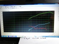
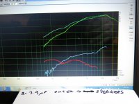
Picture 1) This is a full screen shot. This shows a range from 0dB - 100dB with 10dB increments. A single capacitor, 3.9uF. The outer foil of the capacitor is pointing towards the amplifier. The inner foil proceeds to the tweeter.
The value of 3.9uF is below our ideal of ~4.4uF.
Picture 2) Simply a close up of picture 1.
D3; this distortion stays pretty steady at 20dB. At 5800Hz it drops below the 20dB line.
D2; hits 30dB @ 1800Hz. Rises to 37dB @2700Hz. 40dB @ 6300Hz.
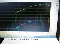
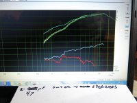
Picture 3) We added our second 3.9uF capacitor to the circuit. There is now a capacitor feeding the positive terminal of the driver, and one feeding the negative terminal. The outer foil of the cap is still pointing towards the amplifier.
D3; 28dB till 1200Hz (not a good start), +8dB. Drops to 20dB for a while, and back up to 27dB. Drops below 20dB @ 4600Hz.
I will postulate capacitors add D3 distortion.
D2; hits 30dB @ 2100Hz (not 1800Hz, therefor better than a single), 37dB @ 4200Hz (also better than at 2700Hz), hits 40dB @ 8000Hz (better by 1700Hz).
I will postulate 'balancing' the signal to the tweeter is better for D2.
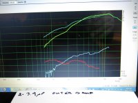
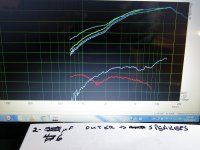
Picture 4) We simply turned our two 3.9uF capacitors around. The outer foil is now at the tweeter end, with the inner foil now pointing to the amplifier.
Stories stories stories. I have so many stories.
When I was a young man, I assumed lightning traveled from the clouds to the ground. It wasn't until I was older that I learned the truth. Current 'first' travels from the ground to the clouds (choosing the path of least resistance, so going to a high point first). This happens at the speed of light, but we don't see current. Almost instantly voltage now travels along the path, from the clouds, ignites air molecules, and we now 'see' the return voltage.
Let's talk amplifiers. I use Tube amplifiers. Tube amplifiers are current source's. Current travels out of the amplifier, so keeping with the laws of physics, voltage travels in the opposite direction (away from the driver, and towards the amplifier).
Capacitors are 'voltage' devises. I've read capacitors sound better when the outer foil is where the voltage enters, and the inner foil for the exodus.
D3; no change. Therefore cap orientation does not affect D3.
D2; hits 30dB @ 2300Hz (just slightly better than 2100Hz, but not a big enough difference). Hits 37dB @ 6500Hz (now that's what I'll call an improvement. 2300Hz after 'foil pointing towards amp' did). Passing 40dB @8200.
All testing from this moment forward will have caps orientated so outer foil is at driver end.
This is only for tube amplifiers. If you are using a voltage source (read solid state amp, the outer foil should point towards the amp).
Someone once said "there is nothing more practical than a really good theory".
Picture 5) A pair of 4.7uF instead of 3.9uF. We are now slightly above our 4.4uF optimal value. The 3.9uF was a Mundorf Silver Oil. The 4.7uF an inexpensive cap.
Opps, have to go to work.
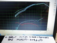
Picture 6) 6uF, which is 2.5 times the status quo.
Picture 7) multistrand wire.
He said "Your additional capacitor on the tweeter will help distortion too".
He may have meant the added slope is good for tweeters, but I'm going to look at the distortion across the entire frequency range. Measurements taken at the tweeter output. Near field (microphone 1" away, well below 1watt)
Let's test his theory.
Let's also see if the outer foil of the capacitor needs to point in a specific direction. (I have read this is important in preamplifiers and amplifiers, but is it important in crossovers?).
Let's see if lower than ideal values and / or higher than ideal values make a difference.
I'm not a fan of multi-strand wiring. Let's see if I can test this.
Time doesn't allow me to test if paralleling two smaller value caps together makes a difference. (again, pre and amplifiers don't like paralleled caps. Is it important in crossovers?). Maybe I'll test that tomorrow.
These measurements are for the tweeter only, with the tweeter caps being changed. Tomorrow I will test the midrange distortion, when changing the tweeter caps. I know it sounds weird, but rigor is necessary.
Picture 1) This is a full screen shot. This shows a range from 0dB - 100dB with 10dB increments. A single capacitor, 3.9uF. The outer foil of the capacitor is pointing towards the amplifier. The inner foil proceeds to the tweeter.
The value of 3.9uF is below our ideal of ~4.4uF.
Picture 2) Simply a close up of picture 1.
D3; this distortion stays pretty steady at 20dB. At 5800Hz it drops below the 20dB line.
D2; hits 30dB @ 1800Hz. Rises to 37dB @2700Hz. 40dB @ 6300Hz.
Picture 3) We added our second 3.9uF capacitor to the circuit. There is now a capacitor feeding the positive terminal of the driver, and one feeding the negative terminal. The outer foil of the cap is still pointing towards the amplifier.
D3; 28dB till 1200Hz (not a good start), +8dB. Drops to 20dB for a while, and back up to 27dB. Drops below 20dB @ 4600Hz.
I will postulate capacitors add D3 distortion.
D2; hits 30dB @ 2100Hz (not 1800Hz, therefor better than a single), 37dB @ 4200Hz (also better than at 2700Hz), hits 40dB @ 8000Hz (better by 1700Hz).
I will postulate 'balancing' the signal to the tweeter is better for D2.
Picture 4) We simply turned our two 3.9uF capacitors around. The outer foil is now at the tweeter end, with the inner foil now pointing to the amplifier.
Stories stories stories. I have so many stories.
When I was a young man, I assumed lightning traveled from the clouds to the ground. It wasn't until I was older that I learned the truth. Current 'first' travels from the ground to the clouds (choosing the path of least resistance, so going to a high point first). This happens at the speed of light, but we don't see current. Almost instantly voltage now travels along the path, from the clouds, ignites air molecules, and we now 'see' the return voltage.
Let's talk amplifiers. I use Tube amplifiers. Tube amplifiers are current source's. Current travels out of the amplifier, so keeping with the laws of physics, voltage travels in the opposite direction (away from the driver, and towards the amplifier).
Capacitors are 'voltage' devises. I've read capacitors sound better when the outer foil is where the voltage enters, and the inner foil for the exodus.
D3; no change. Therefore cap orientation does not affect D3.
D2; hits 30dB @ 2300Hz (just slightly better than 2100Hz, but not a big enough difference). Hits 37dB @ 6500Hz (now that's what I'll call an improvement. 2300Hz after 'foil pointing towards amp' did). Passing 40dB @8200.
All testing from this moment forward will have caps orientated so outer foil is at driver end.
This is only for tube amplifiers. If you are using a voltage source (read solid state amp, the outer foil should point towards the amp).
Someone once said "there is nothing more practical than a really good theory".
Picture 5) A pair of 4.7uF instead of 3.9uF. We are now slightly above our 4.4uF optimal value. The 3.9uF was a Mundorf Silver Oil. The 4.7uF an inexpensive cap.
Opps, have to go to work.
Picture 6) 6uF, which is 2.5 times the status quo.
Picture 7) multistrand wire.
Attachments
- Status
- Not open for further replies.
- Home
- Loudspeakers
- Multi-Way
- 4-Way Series Crossover. Accuton and Acoustic Elegance Drivers