Amongst the chaos, I see order.
Expanding of the Dual Cascade Fully Balanced Paralleled Series Crossover.
It was the Tweeter/Midrange that caught my eye.
This might be called reverse engineering.
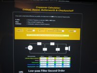
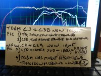
Picture (1) is from the mhaudio website. We know our inductor L1 is 0.3mH. We know we are crossing at 4200Hz. We like the trace with a 4.7uF capacitor. What caught my eye was the resistance necessary for this scenario. Why did the computer suggest a value of 7.9ohms?.
When I go to the Accuton website, I look at the impedance trace for the tweeter. Their measurements show a value around 6.8ohms at 4200hz. The value for the adjacent driver, the C50, is 9.0Ohms, at 4200Hz. If we simply add these two together, and divide by 2, we see the average for these two drivers, at that frequency, is 7.9ohms. Hmmmmmmm?
It was blind luck that 4.7uF was the target cap value. This is a standard value, and I don't expect our luck to hold out.
I will insert different cap values, and see if the crossover point is changed, or just the slope.
In my picture, when looking at the mhaudio cap and inductor values, remember the caps are double what a parallel crossover would be, and the inductors are half.
Next is the midrange to mid woofer crossover point.
We like the crossover point using a 1.5mH inductor.
We know this point is 1200Hz.
We see that mhaudio say 11.7uF is ideal. We are presently using 17.7uF. This will be changed, and all driver slopes measured. Remember, we are trying to see if a change in one spot results in variations elsewhere.
We know the Accuton C50 is 8.5ohms at 1200 Hz.
So quick math shows us the Acoustic Elegance TD6M is 14.1ohms at 1200Hz.
Some of you are thinking this resistance seems high.
FYI, I use a tube amplifier.
My Atma-Sphere MA1's are OTL (output transformerless). They like higher impedance versus lower impedance. When I first saw an impedance graph for this driver, I knew I had to try it. I have looked for that same impedance graph, but can't find it. I think my 14.1ohm figure is what I saw in that graph (like I can remember that far back, 8-9 months ago. I'm 54, and can't remember stuff from yesterday?).
My woofer boxes are still a week away from completion. Measurements will begin next week.
Welcome to the evolution of what might be the greatest crossover ever conceived for a four way speaker (using the proper drivers of course).
Expanding of the Dual Cascade Fully Balanced Paralleled Series Crossover.
It was the Tweeter/Midrange that caught my eye.
This might be called reverse engineering.
Picture (1) is from the mhaudio website. We know our inductor L1 is 0.3mH. We know we are crossing at 4200Hz. We like the trace with a 4.7uF capacitor. What caught my eye was the resistance necessary for this scenario. Why did the computer suggest a value of 7.9ohms?.
When I go to the Accuton website, I look at the impedance trace for the tweeter. Their measurements show a value around 6.8ohms at 4200hz. The value for the adjacent driver, the C50, is 9.0Ohms, at 4200Hz. If we simply add these two together, and divide by 2, we see the average for these two drivers, at that frequency, is 7.9ohms. Hmmmmmmm?
It was blind luck that 4.7uF was the target cap value. This is a standard value, and I don't expect our luck to hold out.
I will insert different cap values, and see if the crossover point is changed, or just the slope.
In my picture, when looking at the mhaudio cap and inductor values, remember the caps are double what a parallel crossover would be, and the inductors are half.
Next is the midrange to mid woofer crossover point.
We like the crossover point using a 1.5mH inductor.
We know this point is 1200Hz.
We see that mhaudio say 11.7uF is ideal. We are presently using 17.7uF. This will be changed, and all driver slopes measured. Remember, we are trying to see if a change in one spot results in variations elsewhere.
We know the Accuton C50 is 8.5ohms at 1200 Hz.
So quick math shows us the Acoustic Elegance TD6M is 14.1ohms at 1200Hz.
Some of you are thinking this resistance seems high.
FYI, I use a tube amplifier.
My Atma-Sphere MA1's are OTL (output transformerless). They like higher impedance versus lower impedance. When I first saw an impedance graph for this driver, I knew I had to try it. I have looked for that same impedance graph, but can't find it. I think my 14.1ohm figure is what I saw in that graph (like I can remember that far back, 8-9 months ago. I'm 54, and can't remember stuff from yesterday?).
My woofer boxes are still a week away from completion. Measurements will begin next week.
Welcome to the evolution of what might be the greatest crossover ever conceived for a four way speaker (using the proper drivers of course).
Attachments
Last edited:
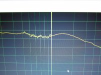
In post #19, I started to deal with the TD6M's 700hz anomaly.
Last night I chamfered the inner edge of the baffle.
This morning, I woke at 4:30 am. Was I that anxious?.
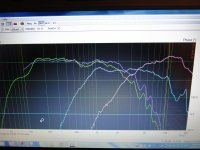
The top line, light green, is right at the phase plug. Chamfered inside baffle. This morning.
The next line, orange, is from a few days ago. This is non-chamfered. It appears to be a little more ragged than the chamfered version. So, chamfering smooth's the response a bit, but we're here for the 700Hz thing.
The third from top, baby blue, is 20" away. This is where the microphone will stay.
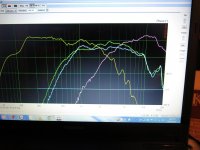
Time to remove the Sorbothane from the magnet. I will be leaving the closed cell foam around the basket base.
I turned the volume down. This might help with room influences.
Both the bottom two traces are smoothed. 20" away. The graph with the bump has the Sorbothane, the graph with no bump has no sorbothane. The sorbothane is gone.
Some of you are thinking, we're done. The second smoothed line worked. Sorry, there was a single spike at 700Hz. This was removed with smoothing.
At that point, this morning, I had to go to work.
Time for another story.
I took the first crew to their jobsite. On my way back to the shop, I started to laugh. It was uncontrollable. I'm sure the people around me thought I was nuts. I moved my head to the right, looked in the rear view mirror, and proclaimed 'YOU IDIOT'.
The 700Hz anomaly is coming from the spider. This spider, which centers the moving parts, is glued to a subframe. The 700Hz anomaly is a reflection from this subframe. It hits the underside of the driver cone, causes the voice coil to move slightly, and there's our impedance blip.
Next post in 20 minutes. Time to go down stairs, remove the driver, put a bit of something on the spider centering ring, and measure.
One of two things will happen;
1) I'm an idiot for not seeing this sooner,
2) It doesn't work after this silly story, which means I'm an idiot,
either way, my wife is right.
Last night I chamfered the inner edge of the baffle.
This morning, I woke at 4:30 am. Was I that anxious?.
The top line, light green, is right at the phase plug. Chamfered inside baffle. This morning.
The next line, orange, is from a few days ago. This is non-chamfered. It appears to be a little more ragged than the chamfered version. So, chamfering smooth's the response a bit, but we're here for the 700Hz thing.
The third from top, baby blue, is 20" away. This is where the microphone will stay.
Time to remove the Sorbothane from the magnet. I will be leaving the closed cell foam around the basket base.
I turned the volume down. This might help with room influences.
Both the bottom two traces are smoothed. 20" away. The graph with the bump has the Sorbothane, the graph with no bump has no sorbothane. The sorbothane is gone.
Some of you are thinking, we're done. The second smoothed line worked. Sorry, there was a single spike at 700Hz. This was removed with smoothing.
At that point, this morning, I had to go to work.
Time for another story.
I took the first crew to their jobsite. On my way back to the shop, I started to laugh. It was uncontrollable. I'm sure the people around me thought I was nuts. I moved my head to the right, looked in the rear view mirror, and proclaimed 'YOU IDIOT'.
The 700Hz anomaly is coming from the spider. This spider, which centers the moving parts, is glued to a subframe. The 700Hz anomaly is a reflection from this subframe. It hits the underside of the driver cone, causes the voice coil to move slightly, and there's our impedance blip.
Next post in 20 minutes. Time to go down stairs, remove the driver, put a bit of something on the spider centering ring, and measure.
One of two things will happen;
1) I'm an idiot for not seeing this sooner,
2) It doesn't work after this silly story, which means I'm an idiot,
either way, my wife is right.
Attachments
It worked.
The 700Hz thing is gone.
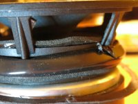
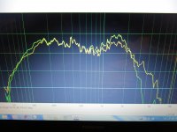
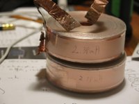
Picture 1) Close up of TD6M basket. Look at the size of the basket posts. I put a little mini piece of closed cell stuff on the posts. I also wrapped a long piece along the inside edge of the spider housing. Sound easy?, you try doing it with big calloused roofers fingers.
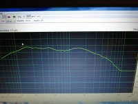
Picture 2) response, 1/24th of an octave gates. Nice.
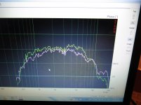
Picture 3) smoothed.
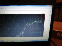
Picture 4) 400hz - 1000Hz, 1/48th of an octave gates.
Time to get back to crossover work.
We already know two of the capacitor values are way off.
The 700Hz thing is gone.
Picture 1) Close up of TD6M basket. Look at the size of the basket posts. I put a little mini piece of closed cell stuff on the posts. I also wrapped a long piece along the inside edge of the spider housing. Sound easy?, you try doing it with big calloused roofers fingers.
Picture 2) response, 1/24th of an octave gates. Nice.
Picture 3) smoothed.
Picture 4) 400hz - 1000Hz, 1/48th of an octave gates.
Time to get back to crossover work.
We already know two of the capacitor values are way off.
Attachments

Housekeeping, and getting a few things off my chest.
In post 20, I said a driver should be looked at as a full wave bridge rectifier. I would like to remove that line. I do believe a gifted programmer will understand adding zener diodes to represent how a driver behaves, just not a FWBR.
SERIES CROSSOVERS????
I just tested the TD6M by itself. What does that mean?. I kept the driver connected to the series crossover, but I disconnected the rest of the drivers. It tested just fine!!!!!!. Part of me wants to scream. Since the dawn of time we've been cautioned. To test a series crossover, all the drivers need to be connected. I'll go downstairs and test the C50 and BD20 as well. At this point I will join the conspiracy theory clan.
Next point. I have used a few capacitor values that are wayyyyyy off. Where's this huge rise/dip that everyone says exists. If any series crossover was going to show this 'problem', mine would have. At this point I have come to a conclusion. Series crossovers are so superior to parallel, that without all this misinformation no one would ever sell parallel crossover programs. I've wasted 8 years trying to make parallels sound fabulous.
My series crossover makes the free air resonance issue a moot point. It doesn't exist or show itself in a Dual Cascade Fully Balanced Paralleled Series Crossover (DCFBPS).
Downstairs I go.
Attachments
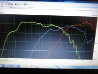
What the heck happened?
I know it's only 5:30 in the morning, but ????
Picture 1) This mornings measurement
OK, the tweeter to midrange looks the same. How did the midrange to midwoofer crossover point move to 2300Hz?
Let's check our driver solder joints.
Let's take our emery cloth and re sand all our crossover copper (except of course those ends soldered together). It's hard to believe 2 weeks after sanding and cleaning the copper inductors, that copper oxide could make this big a difference.
Attachments
Time to move forward.
Everything checked.
I'm going to chalk this up to drivers breaking in????
Tonight's measurement posted.
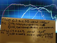
Time to start varying the capacitors.
We now know the 150uF cap which feeds the mid woofer should be closer to 100uF.
Be back in 20 minutes with measurements.
Everything checked.
I'm going to chalk this up to drivers breaking in????
Tonight's measurement posted.
Time to start varying the capacitors.
We now know the 150uF cap which feeds the mid woofer should be closer to 100uF.
Be back in 20 minutes with measurements.
Attachments

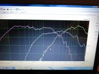
It's time to start optimizing the capacitors.
The first change is C3, and C3B. These are the caps that feed the TD6M Mid Woofer. We've been using 150uF, but we know 100uF is better.
Picture 1) The low end of the TD6M changed slightly, but no change elsewhere.
Picture 2) The C50 Midrange showed absolutely no change. I will postulate that the woofer would have changed. Should really finish the woofer box.
When designing a 2-way, every change of parts is dramatic. With this 4-way, parts changes only affects the adjacent driver. Capacitors affect the lower end of the driver (high pass), with inductors affecting the high end of the driver (low pass). A capacitor change will affect the driver below it, an inductor change will affect the driver above it.
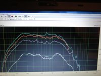
Picture 3) We have now changed C2 and C2B from 17.7uF to 10uF. The C50 midrange has higher output from 700Hz to 1800Hz. There is also a slight rise above 6000Hz.
Picture 4) The mid woofer (TD6M) is the adjacent driver. There was a rise at it's upper end. We don't want this. Tomorrow morning I'll lower the inductor L2 and L2B.
I've been listening to a fair bit of music. I wonder if the breaking in of the drivers is causing some shifts?. I have no other explanation. There should be no change from one day to the next when nothing has been changed.
Having fun.
The first change is C3, and C3B. These are the caps that feed the TD6M Mid Woofer. We've been using 150uF, but we know 100uF is better.
Picture 1) The low end of the TD6M changed slightly, but no change elsewhere.
Picture 2) The C50 Midrange showed absolutely no change. I will postulate that the woofer would have changed. Should really finish the woofer box.
When designing a 2-way, every change of parts is dramatic. With this 4-way, parts changes only affects the adjacent driver. Capacitors affect the lower end of the driver (high pass), with inductors affecting the high end of the driver (low pass). A capacitor change will affect the driver below it, an inductor change will affect the driver above it.
Picture 3) We have now changed C2 and C2B from 17.7uF to 10uF. The C50 midrange has higher output from 700Hz to 1800Hz. There is also a slight rise above 6000Hz.
Picture 4) The mid woofer (TD6M) is the adjacent driver. There was a rise at it's upper end. We don't want this. Tomorrow morning I'll lower the inductor L2 and L2B.
I've been listening to a fair bit of music. I wonder if the breaking in of the drivers is causing some shifts?. I have no other explanation. There should be no change from one day to the next when nothing has been changed.
Having fun.
Attachments
Hi Cousin Billy, Where did you learn this stuff? Most of your explanations on amp/driver workings in post 20 are incorrect, but I see that you have realised that already.
Many years ago I build a 4 way speaker with series filters. No Computers to do the simulations or the measuring. Only a few formulas, a calculator and an analogue volt meter. In its simplest form, the filter components are in series with one driver and parallel to another driver. Changing the value of one component will alter the frequency and phase response of two drivers.
Why are you sanding the inductors? The copper has a transparent coating.
Good morning Mark
Before I tell you about my dream last night, or more accurately, a final thought, let me answer your questions.
Post #20 was quite long.
You said "explanation of amp/driver workings is wrong". I am unsure which part was wrong?.
If my understanding of the amp/driver relationship is wrong, than my explanation simply helped me visualize the relationship.
You said "Many years ago I build a 4 way speaker with series filters. No Computers to do the simulations or the measuring. Only a few formulas, a calculator and an analogue volt meter. In its simplest form, the filter components are in series with one driver and parallel to another driver. Changing the value of one component will alter the frequency and phase response of two drivers."
This statement by you will be talked about in the next post. Your use of both words, series and parallel will be expanded upon, and tested.
An inductor starts as a very long piece of wire. It is then wound around and around. Any part which comes in contact with another part is coated, or a piece of something is placed between them (thin plastic, wax paper, etc.). Now we come to the two ends. These ends are outside the 'inductance producing portion' of the inductor. If a coating was used, then no voltage or current can escape. This coating (visualize magnet wire or Litz wire,) needs to be removed. If it's not, it won't allow anything to pass. You need to clean off the coating to use the inductor. In the case of my copper foil air core inductors, there is no coating. However, copper oxide does not conduct electricity. We need to occasionally sand off this 'rust'. You should ALWAYS cleans all your ends before soldering.
A capacitor starts out as TWO long pieces of wire. The end going in one side, ends inside the capacitor, and is attached to nothing. The other wire starts just inside the sealed end, is wrapped with the other wire, and it's end is what comes out the other side. I think????
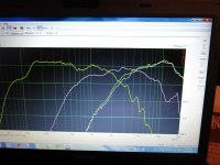
In post #28, describing picture 4, my final words; "lower the inductor L2 and L2B". This will change the TD6M mid woofers upper frequencies.
What was I thinking. Lowering this inductor value will allow MORE high frequencies to get to this driver. What I need to do is INCREASE the inductor values, and lower the frequencies.
Wait a second, if I increase the value, then my series crossover thought process is all wrong. At mhaudio I would have to have a monster resistance at 1200Hz, like 30 ohms.
Here's my dream (final thought); for a 4-way dual cascade paralleled series crossover, what if the middle drivers, like the C50 midrange and the TD6M mid woofer, get treated like parallel crossovers. Could I have added the 'paralleled' word in my crossover description as a joke, when in actual fact, it's needed??????
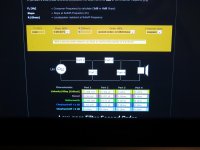
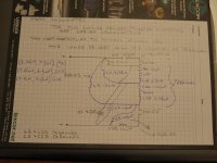
Picture 1) It's been a while since we saw our final crossover topology.
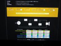
Picture 2) For a parallel crossover, mhaudio tells us we need to use an inductor, L2, of 2.38mH (I just happen to have a couple of those?). We know the Accuton C50 is around 8.5 ohms. In the mhaudio resistance box I put 9 ohms. This assumes the TD6M is 9.5 ohms at 1200Hz. The next few pictures simply raise the resistance so we can check other stuff.
Picture 3) Averaged resistance now 10 ohms
Picture 4) Averaged resistance now 11 ohms.
Picture 5) Mark, this is for you. If you look at the ends of the inductor, the left side is really shiny. This is what your inductors need to look like before soldering. The first time you solder to a freshly sanded copper surface, you will be amazed how the solder flux truly draws the solder into the metal. I NEVER use the inductor manufacturers tinned ends. Cut it away, sand a new surface.
Time for breakfast, then testing my theory.
With all this personal stuff, you'd think this was facebook. OMG, did you see her purse??
What was I thinking. Lowering this inductor value will allow MORE high frequencies to get to this driver. What I need to do is INCREASE the inductor values, and lower the frequencies.
Wait a second, if I increase the value, then my series crossover thought process is all wrong. At mhaudio I would have to have a monster resistance at 1200Hz, like 30 ohms.
Here's my dream (final thought); for a 4-way dual cascade paralleled series crossover, what if the middle drivers, like the C50 midrange and the TD6M mid woofer, get treated like parallel crossovers. Could I have added the 'paralleled' word in my crossover description as a joke, when in actual fact, it's needed??????
Picture 1) It's been a while since we saw our final crossover topology.
Picture 2) For a parallel crossover, mhaudio tells us we need to use an inductor, L2, of 2.38mH (I just happen to have a couple of those?). We know the Accuton C50 is around 8.5 ohms. In the mhaudio resistance box I put 9 ohms. This assumes the TD6M is 9.5 ohms at 1200Hz. The next few pictures simply raise the resistance so we can check other stuff.
Picture 3) Averaged resistance now 10 ohms
Picture 4) Averaged resistance now 11 ohms.
Picture 5) Mark, this is for you. If you look at the ends of the inductor, the left side is really shiny. This is what your inductors need to look like before soldering. The first time you solder to a freshly sanded copper surface, you will be amazed how the solder flux truly draws the solder into the metal. I NEVER use the inductor manufacturers tinned ends. Cut it away, sand a new surface.
Time for breakfast, then testing my theory.
With all this personal stuff, you'd think this was facebook. OMG, did you see her purse??
Attachments

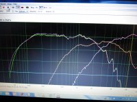
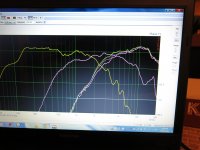
That was a long day of testing. I think I'm punch drunk.
Caveat 1. I finally removed my second 12mH inductor from an old project. You'll see the lower end (150Hz area) of the TD6M mid woofer a little different. There is also slightly more energy from there up. Until I finish the woofer box, I'm not going to worry about it.
Caveat 2. These are near field measurements, 3" microphone distance. In the back of our minds we need to remember the Baffle Step. Baffle loss'. Another fun part will be when I start testing different baffle angles to maximize acoustic centers.
Picture 1) I jotted a few thoughts on paper. Some of the values have been changed. They reflect our belief the center drivers need to be treated as parallel drivers, not series. This belief is for 4-way and higher speakers. I have to think about this before I can comment on 3-ways.
Picture 2) The mid woofers inductors are now 2.38mH (assuming we treat it like a parallel driver). We've left C2 and C2B at 10uF. The picture shows the bump at and above 1000Hz is getting better. This might indicate that 'parallel' crossover calculations might be the way to go.
Picture 3) This is the output from the midrange with the mid woofer inductor change. There is a fair bit more energy above 1500Hz. I think I like this.
Picture 4) This is the tweeter measurement. There is a slight change. This perplexes me. May I chalk it up to gremlins?
We are now going to change the midranges capacitors. We're going from 10uF to 6.8uF. If you look at my first picture today, you'll see I should be trying a 7.4uF cap. I don't have one, so 6.8uF it is.
Picture 5) This is again the tweeter. The less moving of the microphone I do the more accurate some traces will be. The tweeter now cross' in the 3800Hz area. The tweeter now has a bit too much output. I don't think I like this value.
Picture 6) The midrange with 6.8uF. Nope.
Let's change that same cap to 8.2uF
Picture 7) This trace for the midrange looks good. Let's leave it.
Picture 8) The mid woofer, 2.38mH, 8.2uF, not much change from 10uF. This was expected.
There's still one thing I don't like. The mid woofer has too much output in that 1000Hz area.
If I have time tonight I'll try 2.7mH (L2, L2B). This might need the cap (C2 and C2B) to go to 6.8uF.
I think we're getting down to the nitty gritty.
Attachments
Truly amazing.
Just listened to Sonny Boy Williamson, Lucinda Williams, and Keb' Mo'.
Could have listened all night.
Not in my wildest dreams could I have expected this. Phase perfect, no intermodulation distortion, and dynamics to die for.
More testing tomorrow
Just listened to Sonny Boy Williamson, Lucinda Williams, and Keb' Mo'.
Could have listened all night.
Not in my wildest dreams could I have expected this. Phase perfect, no intermodulation distortion, and dynamics to die for.
More testing tomorrow
How do you combine series and parallel drivers/filters?
If you take this back to something more understandable, like two drivers in series with a capacitor parallel over the woofer and an inductor parallel over the tweeter. Changing the value of either will move the F3 and the phase response of both the drivers.
The capacitor is in series with the tweeter and parallel to the woofer.
Adding the extra filter components by the drivers (the ones with a B) changes the roll-off by 6 dB per octave as well as the phase.
Last edited:
How do you combine series and parallel drivers/filters?
If you take this back to something more understandable, like two drivers in series with a capacitor parallel over the woofer and an inductor parallel over the tweeter. Changing the value of either will move the F3 and the phase response of both the drivers.
The capacitor is in series with the tweeter and parallel to the woofer.
Adding the extra filter components by the drivers (the ones with a B) changes the roll-off by 6 dB per octave as well as the phase.
Good morning Mark
You're correct, I have a poor way of explaining myself.
My memory is this; with a series crossover, we're taught to half inductor values, and double capacitor values. The initial values come from parallel crossover calculations. This is where we started. This halving and doubling is for a 2-way. I assumed this would also be true for a 3-way and up.
With a dual cascade 4-way, I'm finding something different. The center drivers should have parallel crossover calculations applied. No halving or doubling.
I'm unsure if I've ever read this elsewhere.
Last night I made changes, and measured. I spent the remainder of the evening with jaw firmly planted on the floor. The music just flowed.
This morning I'm going to make a few other changes, and measure.
See you all soon.
Seems like a lot of really expensive drivers and time spent fiddling when some modeling software and good measurements will get you the response you want in an afternoon.Then you can fine tune from there. I don't think your method is doing justice to the drivers.
Hi,
Yes. Some rigour rather than totally extensive waffle
would help doing some real justice to the drivers.
"with a series crossover, we're taught to half inductor values, and double
capacitor values. The initial values come from parallel crossover calculations."
Complete nonsense, as is much of your half baked musings.
rgds, sreten.
Seems like a lot of really expensive drivers and time spent fiddling when some modeling software and good measurements will get you the response you want in an afternoon.Then you can fine tune from there. I don't think your method is doing justice to the drivers.
augerpro and sreten, you are both correct.
I have two design parameters 1) dual cascade, 2)balanced.
I queried three crossover people for help. One responded, the picture was with some of my hand drawn schematics. Two others, no response.
I would love to find a series crossover simulation that will accept my two parameters.
Back to my woofer boxes, and watching the Toronto Blue Jays.
You asked Bohdan of Soundeasy?
Just spent a couple of hours on the Soundeasy website. Quite impressive. I myself am a Geophysicist. Unfortunately a computer program was written that diminished our necessity. Now I'm a roofer (pays for my audio addiction).
I will definitely contact him regarding a simulation. Ad nauseam; Dual Cascade, Balanced, Series.
Last night I raised one of the inductor values to 2.7mH. For me that was aurally a win. I listened for hours, you know what my impression was.
This morning I remembered I also have a pair of 2.7mH Mundorf vacuum impregnated cored inductors (not copper foil air cored).
I listened to a lot of music today.
With the cored inductor the weight and articulation in the mid-base was better, but I'm not sure if I'm 100% certain it's good for the higher TD6m frequencies.
I will listen to the cored inductor for a few days, switch back to the copper foil air core inductors, and report what I think I hear.
Last edited:
- Status
- Not open for further replies.
- Home
- Loudspeakers
- Multi-Way
- 4-Way Series Crossover. Accuton and Acoustic Elegance Drivers