There are advantages to getting old. No more worries about kids, cars, houses etc.. Mental freedom. Add the rise in disposable income, and here we are.
I've always been intrigued by Series Crossovers. Tony G. at humble homemade hifi still uses them, and I respect him. His, and Troels G's website have been true inspirations. Enough mush.
A few years ago I drank too much red wine. I ended up writing something down. "the inductors feed the top of the driver, the capacitors feed the bottom of the drivers. There is no ground". I couldn't remember exactly what I was thinking.
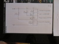
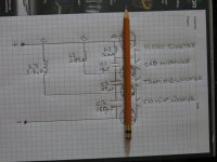
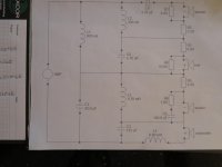
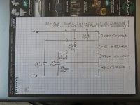
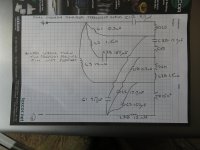
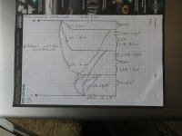
Shortly thereafter I figured it out, and jotted down a crossover. The initial values are just a starting point. The L1 of 0.1mH comes from the old AR-SXO crossover. L2 of 0.68mH just seemed close. L3 of 5.6mH is a value I had on hand. The capacitors for this initial test are twice what they should be. Hopefully my theories are correct.
My simple thoughts; the inductors set the crossover points, the capacitors save the amps from shorting out. The capacitors should only help with crossover slopes, they should never change the frequencies the driver uses.
This point is important; an amplifier has no ground. The positive terminal manipulate the positive portion of the waveform, the negative terminal manipulates the negative portion of the waveform.
Once the energy is in the system, one of the drivers needs to use it. This is a little different from a parallel crossover. It is my belief that caps that are too small destroy the flow of energy (current).
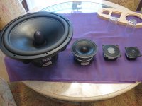
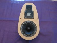
Accuton BD20 tweeter
Accuton C50 2" midrange (Troels called it the best midrange he's ever used) I wanted the newer C51, but it took forever to get here. Baffles where already made.
Acoustic Elegance TD6M 6" midrange. I wanted this for it's large mechanical x-max. I have read back EMF is bad for series crossover. One way to minimize this is with large x-max.
Acoustic Elegance TD15H+. Looking forward to hearing this monster.
Explaining my crossover schematic.
1) Let's take an arbitrary high frequency. 15,000Hz. The positive portion of this frequency comes from the +ve terminal of the amp. As this signal enters the circuit, it is blocked from going down 'C' (5.6mH). It continues to 'B' where it is also mostly blocked. L1 also blocks most, so off to the tweeter it goes.
At this point we still don't hear anything. The tweeter now needs the -ve portion of the waveform. The -ve terminal of the amplifier provides this, and the caps gladly let it pass through. We have sound.
2) Our second arbitrary frequency. 3,000Hz. The positive portion comes out of the amp. 'C' blocks it, 'B' mostly blocks it, 'A' gladly lets it pass. It can also go to the tweeter, but the tweeter has Re. This resistance helps direct the signal to the top of the midrange.
Again, we now need the -ve portion, which easily passed through the capacitors.
3) Our third arbitrary frequency. 1,500Hz. This makes it to the midwoofer through 'B', the 0.68mH inductor. You know the rest.
4) The woofer sees whatever passes through L3 of 5.6mH. The -ve portion can't have a cap in the way, obviously.
How to test this?
All the drivers need to be connected. This is the only drawback of trying to test a series crossover speaker. We don't want to test all the drivers at once, we want to test them individually. We set up a second speaker in an adjacent room. Run long wires. Wire one driver at a time in the microphone room. I love alligator clips.
Time to measure.
I've always been intrigued by Series Crossovers. Tony G. at humble homemade hifi still uses them, and I respect him. His, and Troels G's website have been true inspirations. Enough mush.
A few years ago I drank too much red wine. I ended up writing something down. "the inductors feed the top of the driver, the capacitors feed the bottom of the drivers. There is no ground". I couldn't remember exactly what I was thinking.
Shortly thereafter I figured it out, and jotted down a crossover. The initial values are just a starting point. The L1 of 0.1mH comes from the old AR-SXO crossover. L2 of 0.68mH just seemed close. L3 of 5.6mH is a value I had on hand. The capacitors for this initial test are twice what they should be. Hopefully my theories are correct.
My simple thoughts; the inductors set the crossover points, the capacitors save the amps from shorting out. The capacitors should only help with crossover slopes, they should never change the frequencies the driver uses.
This point is important; an amplifier has no ground. The positive terminal manipulate the positive portion of the waveform, the negative terminal manipulates the negative portion of the waveform.
Once the energy is in the system, one of the drivers needs to use it. This is a little different from a parallel crossover. It is my belief that caps that are too small destroy the flow of energy (current).
Accuton BD20 tweeter
Accuton C50 2" midrange (Troels called it the best midrange he's ever used) I wanted the newer C51, but it took forever to get here. Baffles where already made.
Acoustic Elegance TD6M 6" midrange. I wanted this for it's large mechanical x-max. I have read back EMF is bad for series crossover. One way to minimize this is with large x-max.
Acoustic Elegance TD15H+. Looking forward to hearing this monster.
Explaining my crossover schematic.
1) Let's take an arbitrary high frequency. 15,000Hz. The positive portion of this frequency comes from the +ve terminal of the amp. As this signal enters the circuit, it is blocked from going down 'C' (5.6mH). It continues to 'B' where it is also mostly blocked. L1 also blocks most, so off to the tweeter it goes.
At this point we still don't hear anything. The tweeter now needs the -ve portion of the waveform. The -ve terminal of the amplifier provides this, and the caps gladly let it pass through. We have sound.
2) Our second arbitrary frequency. 3,000Hz. The positive portion comes out of the amp. 'C' blocks it, 'B' mostly blocks it, 'A' gladly lets it pass. It can also go to the tweeter, but the tweeter has Re. This resistance helps direct the signal to the top of the midrange.
Again, we now need the -ve portion, which easily passed through the capacitors.
3) Our third arbitrary frequency. 1,500Hz. This makes it to the midwoofer through 'B', the 0.68mH inductor. You know the rest.
4) The woofer sees whatever passes through L3 of 5.6mH. The -ve portion can't have a cap in the way, obviously.
How to test this?
All the drivers need to be connected. This is the only drawback of trying to test a series crossover speaker. We don't want to test all the drivers at once, we want to test them individually. We set up a second speaker in an adjacent room. Run long wires. Wire one driver at a time in the microphone room. I love alligator clips.
Time to measure.
Attachments
I'm very happy with my measurements, and there's already a caveat.
My woofer cabinets are not yet finished. The TD15H+ is in the back room running free.
These measurements have the woofer connected, but not in the main room.
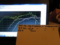
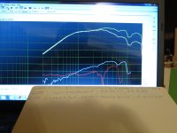
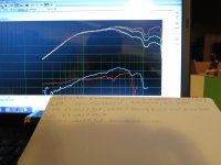
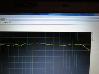
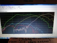
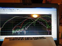
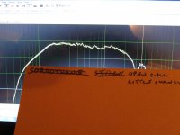
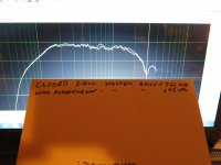
The first picture is of three of the drivers. The tweeter, midrange, and mid-woofer. These are raw measurements in the cabinets. I used a cap for the midrange and tweeter. I have a lively listening room, so I test lower than 1 watt. Microphone was at 6 inches from the drivers.
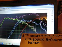
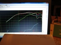
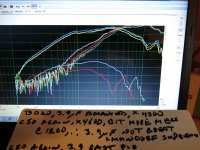
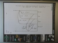
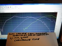
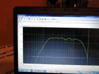
The second picture includes the drivers in circuit with their raw measurements included. Crossover is at 1200Hz and 4800Hz. Not a bad start.
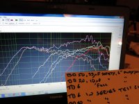
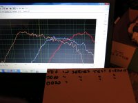
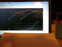
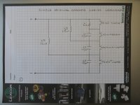
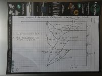
The third picture is of the three drivers in circuit.
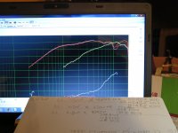
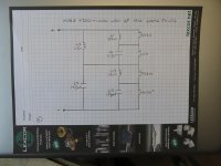
Picture 4 is with the second inductor, L2, changed to 1.0mH. With this value the crossover from the mid-woofer to mids has dropped too much. We are now at 875Hz. I will need to listen to music before I say it's too low.
My woofer cabinets are not yet finished. The TD15H+ is in the back room running free.
These measurements have the woofer connected, but not in the main room.
The first picture is of three of the drivers. The tweeter, midrange, and mid-woofer. These are raw measurements in the cabinets. I used a cap for the midrange and tweeter. I have a lively listening room, so I test lower than 1 watt. Microphone was at 6 inches from the drivers.
The second picture includes the drivers in circuit with their raw measurements included. Crossover is at 1200Hz and 4800Hz. Not a bad start.
The third picture is of the three drivers in circuit.
Picture 4 is with the second inductor, L2, changed to 1.0mH. With this value the crossover from the mid-woofer to mids has dropped too much. We are now at 875Hz. I will need to listen to music before I say it's too low.
Attachments
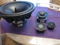
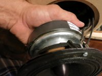
The 4 drivers.
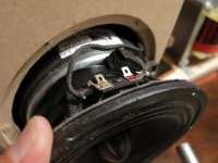
If we look at the 6" Acoustic Elegance TD6M, we notice a very large magnet structure.
When I first received this driver, I did a quick measurement. There was a dip at 700Hz. This dip is well documented on other sites.
How to lessen this dip?
I thought, could it be a reflection from the top surface of the magnet?
I had some Sorbothane lying around, so I wrapped the magnet. There is a 'lip' extending up towards the spider.
If we look at the measurement graph, we see a 'rise' at 700Hz.
In the future I will experiment with various 'absorbing' things to put on the magnet.
Off to work.
Attachments
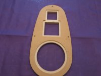
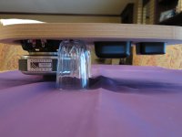
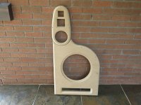
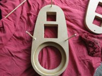
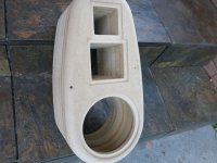
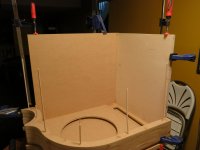
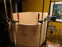
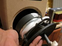
Some pictures of the test boxes.
In reality, the things that will change include; the baffle (1" mdf is not ideal), stuffing, bracing, time alignment sloping of upper baffle if necessary, driver distance between the mid-woofer and midrange.
I've used aluminum baffles in the past, unlikely ever again.
I like the idea of Tankwood (Panzerholz?). Cost may be outrages.
The upper section is at the point where I can test.
The lower section is still a while away.
Attachments
My simple thoughts; the inductors set the crossover points, the capacitors
save the amps from shorting out. The capacitors should only help with
crossover slopes, they should never change the frequencies the driver uses.
Hi,
Capacitors affect the x/o point. Model it in (free) TinaTi.
With resistors 1st order series and parallel are identical.
But you can't offset x/o points in series like in parallel.
However with real drivers 1st order series is very different.
Your cascaded topology strictly speaking is not 1st order.
rgds, sreten.
Amplifier grounding arrangement are irrelevant.
Usually black is ground except for bridged.
Last edited:
sreten, time to test if the capacitors should be used to change the crossover point.
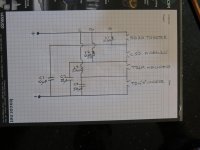
Picture 1) I have drawn a new schematic. The midrange is now labelled properly, C50. The largest capacitor, C3, is now 150uF. When I made this change, and measured, nothing changed. L2 is now 0.82mH.
Picture 2) I did a simulation a while back. This helped me with my starting points, as long as I had the parts in house.
Picture 3) A different layout. I will wait until I have narrowed down the values. I will start doing more listening at this point.
Picture 4) This is the Accuton C50 midrange, in circuit, C1 of 10uF. Distortion D2 and D3 do not hit the 50dB line. I should have taken a wider shot to include the scale.
Picture 5) I dropped C1 by quite a bit, it's now 2.7uF. This is lower than one would use. The crossover point turns out to be 9000Hz (I'll include that picture shortly). There is a marked rise in output up to 9000Hz. There is also a slight rise in D2, up to 54dB. D3 is lower below 1000Hz, and slightly higher above 4000Hz.
Picture 6) This is our simulation ideal C1 of 4.7uF
Picture 7) The Accuton BD20 tweeter. C1 of 10uF. Crossover at 4800Hz. D2 peak at 57dB. D3 comes back and hits 30dB.
Picture 8) The tweeter with C1 our theoretical ideal of 4.7uF. Cross at 6200Hz. D2 is unchanged, D3 is lower.
Picture 9) C1 2.7uF. cross at 9000Hz.
sreten. You where right (I concede, you are rarely wrong). The cap can also be used to set the crossover. Distortion appears to be slightly lower when the cap is chosen correctly.
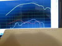
Last picture is all three drivers wired in the circuit. 20 inch microphone distance. Woofer doesn't have it's box, so is not included. I don't often use smoothing, but it looks pretty. 1/3octave smoothing used.
I see a slight dip in the midrange/tweeter area. Maybe lowering my 10uF C1 to 4.7uF will raise this slightly?. Maybe raising my inductor L1 from 0.1mH to 0.2mH will still result in a ~5000Hz crossover.
Lots of work still to do.
Again, sreten, thank you.
Picture 1) I have drawn a new schematic. The midrange is now labelled properly, C50. The largest capacitor, C3, is now 150uF. When I made this change, and measured, nothing changed. L2 is now 0.82mH.
Picture 2) I did a simulation a while back. This helped me with my starting points, as long as I had the parts in house.
Picture 3) A different layout. I will wait until I have narrowed down the values. I will start doing more listening at this point.
Picture 4) This is the Accuton C50 midrange, in circuit, C1 of 10uF. Distortion D2 and D3 do not hit the 50dB line. I should have taken a wider shot to include the scale.
Picture 5) I dropped C1 by quite a bit, it's now 2.7uF. This is lower than one would use. The crossover point turns out to be 9000Hz (I'll include that picture shortly). There is a marked rise in output up to 9000Hz. There is also a slight rise in D2, up to 54dB. D3 is lower below 1000Hz, and slightly higher above 4000Hz.
Picture 6) This is our simulation ideal C1 of 4.7uF
Picture 7) The Accuton BD20 tweeter. C1 of 10uF. Crossover at 4800Hz. D2 peak at 57dB. D3 comes back and hits 30dB.
Picture 8) The tweeter with C1 our theoretical ideal of 4.7uF. Cross at 6200Hz. D2 is unchanged, D3 is lower.
Picture 9) C1 2.7uF. cross at 9000Hz.
sreten. You where right (I concede, you are rarely wrong). The cap can also be used to set the crossover. Distortion appears to be slightly lower when the cap is chosen correctly.
Last picture is all three drivers wired in the circuit. 20 inch microphone distance. Woofer doesn't have it's box, so is not included. I don't often use smoothing, but it looks pretty. 1/3octave smoothing used.
I see a slight dip in the midrange/tweeter area. Maybe lowering my 10uF C1 to 4.7uF will raise this slightly?. Maybe raising my inductor L1 from 0.1mH to 0.2mH will still result in a ~5000Hz crossover.
Lots of work still to do.
Again, sreten, thank you.
Attachments
-
 IMG_0624.jpg836.8 KB · Views: 232
 -
 IMG_0612.jpg549.9 KB · Views: 185
 -
 IMG_0623.jpg693.3 KB · Views: 185
 -
 IMG_0630.jpg888.8 KB · Views: 173
 -
 IMG_0631.jpg771.8 KB · Views: 129
 -
 IMG_0634.jpg680.2 KB · Views: 93
 -
 IMG_0635.jpg875.2 KB · Views: 92
 -
 IMG_0636.jpg729 KB · Views: 97
 -
 IMG_0637.jpg744.9 KB · Views: 90
 -
 IMG_0640.jpg990.2 KB · Views: 136
Billy is obviously showing acoustical measurements? The nonlinearity of a driver's output must be implemented in the electrical crossover circuit. Then xo-point definition is not as easy as sreten writes.
3/4-way speakers usually have relatively smooth directivity characteristis, which makes design easier than in a 2-way case. Easier in a way, but more work...
What about total impedance and phase?
3/4-way speakers usually have relatively smooth directivity characteristis, which makes design easier than in a 2-way case. Easier in a way, but more work...
What about total impedance and phase?
Billy is obviously showing acoustical measurements? The nonlinearity of a driver's output must be implemented in the electrical crossover circuit. Then xo-point definition is not as easy as sreten writes.
3/4-way speakers usually have relatively smooth directivity characteristis, which makes design easier than in a 2-way case. Easier in a way, but more work...
What about total impedance and phase?
Juhazi
I am going to evade your question about impedance and phase.
Let me explain.
A long time ago I read an article. This article was at esp (Elliot Sound Productions, I think). That article was 'series vs parallel crossovers'. It was a good read, and I recommend it to everyone.
Nearing the end of the article they show a graph on impedance. In a parallel crossover, at the crossover point, there is a drop in the woofers impedance. If we look at a 4-way speaker, this dip occurs three times. In a series crossover, at the crossover point, there is a minor ripple. No dip. I move there is no need to measure impedance. I will though, some time next week.
Phase? In that same article, near the above mentioned graph, they show phase. The series crossover is perfect. There is no phase change between the input signal, and the measured output. Series crossovers preserve phase. The only fluctuations will be the drivers natural shift. No way of changing that, I think.
The article implied parallel crossover occasionally need Zobels and such to try and correct phase?.
Or am I completely out to lunch?
Then xo-point definition is not as easy as sreten writes.
Hi,
True. It defines the electrical x/o point, not the acoustic x/o point.
With expensive drivers you really want a full on simulation, with
baffle modelling for BSC and correct driver attenuation in the x/o.
rgds, sreten.
Last edited:
An observation from trying to implement the AR-SXO philosophy.
I've made a lot of measurements. This with L1 at 0.1mH.
When I changed this value to 0.2mH, and re-measured, nothing changed. This indicates to me that 0.1mH, and even 0.2mH, is too low for the Accuton drivers.
I have now measured with L1 at 0.3mH.
My crossover point is now 4200Hz. In my mind I believe it's better to accept where it ends up, and not at where I want it.
Testing was similar to previous tests. Vary a capacitor value, see how the tweeter and mid react.
If we look at the midrange trace, after 10,000Hz, we see a rise.
With a balanced circuit (read second order), using 3.9uF, there is a mild rise at 12,000Hz.
With 4.7uF and 6.0uF, this mini rise is absent. This could indicate to me 4.7 is ideal.
Hold on for a sec.
I think I see something.
I clear a few cobwebs from my oldish head.
I go back and read the esp 'series vs parallel' article.
I now remember the article better.
In a second order series crossover, inductors are halved, and capacitors are doubled (in comparison to a parallel crossover).
I now go to mh_audio dot com. Slope calculation section.
X-over at 4200Hz, 2nd order Linkwitz, Re 7.5Ohms. and what pops up?; L1 of 0.569mH. Let's halve this, and we get 0.2845. My measured best is 0.30mH. Close enough. C1 of 2.5uF. Let's double it, and we get 5.0uF. My value of 4.7 is close enough (for now).
Can series crossovers be this easy?
Mid-woofer to midrange. Our target is 1200Hz. For a parallel crossover mh audio says L2 at 2.0mh, so I should be using 1.0mH for series, and not 0.82mH. mh says 8.8uF, so time to test my C2 at 17.7uF.
Maybe I should take an impedance measurement. I could enter a more accurate Re into mh_audio calculator.
Time to rewrite my crossover schematic, go back to mh audio for newer values, and test.
See ya'll tomorrow.
Attachments
There where lots of measurements this weekend. I'm squarely in the dog house.
I've narrowed down a few of the value.
L1 (which feeds the Accuton C50 2" midrange) is now 0.3mH. This bypasses frequencies below 4000Hz from the tweeter.
L2 (which feeds the Acoustic Elegance TD6M) is now 1.5mH. This bypasses frequencies below 1200Hz from the midrange.
L3 (which feeds the Acoustic Elegance TD15H+) is now 12mh.
C1 is 4.7uF. This will likely stay. If it varies, it will only be marginally.
C2 is 17.7uF. I will play with this capacitor a lot in the upcoming weeks.
C3 is 106uF. This too will be played with.
As sreten said, the capacitors help change things. I have a few dips and or rises I want to vary.
I tried to upload my original schematic, but it didn't work. It's on the previous page, and it was just for reference.
My thoughts revolve around Tony G's capacitor tests. I am in agreement. Great capacitors do make a difference. I am a fan of the Duelund line.
If we look at my original, simple, schematic, we see three capacitors. They come up from the -ve leg. If I want the best capacitor for my tweeter, and it's a Duelund VSF, why would I be satisfied with the signal going through a large 100+uF MKP first?.
If sreten says my original crossover is a Cascade, than my second thought is a Dual Cascade crossover.
I just tried to upload my crossover schematic. It appears my computer, or the web hoster, is overwhelmed.
I'll try again tomorrow.
For now, I'll listen to my Dual Cascade fully Balanced Paralleled Series Crossover beauties.
This post shows 4 crossover schematics.
In a series crossover, where we simply regulate the flow of current, all four crossover schematics are identical. The fourth drawing is how future drawings will look. This means there are three crossovers.
Testing showed all three crossovers had identical slopes and crossover points.
Listening to music the last week, I have an admission. I am now clearly in the 'series crossover' camp. Move over, pass a marshmallow, and give me my first s'more. Maybe.
Troels called the Accuton C50 midrange the best he's heard. Maybe the improvement from my previous parallel crossover with a 6" Accuton driver to a 3/4" tweeter is because of the mid. At some point in the future I'll try a parallel crossover to see (hear) how it turns out. My hearing is sensitive to intermodulation distortion (possibly phase issues) which is why I am trying this series crossover. I believe my choice of drivers will make parallel crossover modelling quite easy.
Listening to the dual cascade crossover, using great capacitors for the tweeter and midrange, I can say I am in awe of what I'm hearing. It's the best I've ever heard, and I've listened to a lot of speakers. But it's still not perfect. Right now the midrange up is to die for. Below 1000Hz there is a slight dip, but I won't worry about that yet, my woofers still need their cabinets.
From here on I will only be using the dual cascade topology. We have Tony G to blame for this.
Capacitors. As stated, I would like my tweeter and mid range to only 'see' great caps. For the mid-woofer, I will parallel a large MKP with a few Duelund's.
Inductors. I am also in agreement with Tony on the inductor issue. The woofer needs a large transformer style low Rdc inductor. I have a few values of the Mundorf vacuum impregnated variety on hand, and I hope one of these values is the final value. For the mid range and mid woofer, foil air core will be used.
Attachments
Time to move forward.
You'll find this hard to believe, but I have another story.
Years ago I built my first prototype. I think 7-8 years. At that time I saw one of Tony's crossovers. In that crossover there was something I hadn't seen before. The midrange inductor was half of what I expected, but the other half was on the -ve leg. When I emailed him, he told me it was a balanced circuit. He than directed me to the web page with the explanation. The theory appeared sound to me. I changed my crossover to this balanced style, and liked what I heard. My next speaker didn't have room for an extra inductor, so it wasn't balanced.
The target for this series crossover has always been a balanced topology.
L1B is therefore 0.3mH
L2B is 1.5mH
L3B is 12mH
C1B 4.7uF
C2B is 17.7uF
C3B is 106uF
The problem is, where to put them?
Picture 1) This is the first 'balanced' topology test schematic. 6 identical components are added to the crossover (as in L1=0.3mH, so L1B is also 0.3mH). These components are added to the main body of the crossover.
Picture 2) This is here just for comparison. This is the 'non' balanced topology.
Picture 3) First balanced topology test measurements. What the heck happened??????. The red trace is the C50. What's with that big hump below 300Hz. The dark green trace for the tweeter, below 2000Hz????. Light green trace, mid woofer, above 2000Hz is a disaster. Having the second set of capacitors and inductors in the main body of the crossover is just wrong.
Picture 4) Let's move two of the components away from the main body of the crossover. We connect them directly to the drivers. If I was to try to explain this to myself, I would call these second positions correction circuitry positions. I arbitrarily chose to move C2B (17.7uF) and L2B (1.5mH). There was minor improvement, but still not what I would be satisfied with.
If moving two of the components to the drivers showed a small improvement, what would moving the other two result in? (I think you already know the answer).
Picture 5) This is our final topology. The main body of the crossover contain the 6 primary series components (6 for a 4-way speaker). The other 6 'balancing' components are connected to their respective drivers.
Picture 6) These are the measurements.
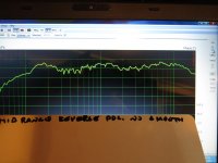
Picture 7) Microphone 20" away, midrange height, no smoothing, midrange reverse polarity.
You'll find this hard to believe, but I have another story.
Years ago I built my first prototype. I think 7-8 years. At that time I saw one of Tony's crossovers. In that crossover there was something I hadn't seen before. The midrange inductor was half of what I expected, but the other half was on the -ve leg. When I emailed him, he told me it was a balanced circuit. He than directed me to the web page with the explanation. The theory appeared sound to me. I changed my crossover to this balanced style, and liked what I heard. My next speaker didn't have room for an extra inductor, so it wasn't balanced.
The target for this series crossover has always been a balanced topology.
L1B is therefore 0.3mH
L2B is 1.5mH
L3B is 12mH
C1B 4.7uF
C2B is 17.7uF
C3B is 106uF
The problem is, where to put them?
Picture 1) This is the first 'balanced' topology test schematic. 6 identical components are added to the crossover (as in L1=0.3mH, so L1B is also 0.3mH). These components are added to the main body of the crossover.
Picture 2) This is here just for comparison. This is the 'non' balanced topology.
Picture 3) First balanced topology test measurements. What the heck happened??????. The red trace is the C50. What's with that big hump below 300Hz. The dark green trace for the tweeter, below 2000Hz????. Light green trace, mid woofer, above 2000Hz is a disaster. Having the second set of capacitors and inductors in the main body of the crossover is just wrong.
Picture 4) Let's move two of the components away from the main body of the crossover. We connect them directly to the drivers. If I was to try to explain this to myself, I would call these second positions correction circuitry positions. I arbitrarily chose to move C2B (17.7uF) and L2B (1.5mH). There was minor improvement, but still not what I would be satisfied with.
If moving two of the components to the drivers showed a small improvement, what would moving the other two result in? (I think you already know the answer).
Picture 5) This is our final topology. The main body of the crossover contain the 6 primary series components (6 for a 4-way speaker). The other 6 'balancing' components are connected to their respective drivers.
Picture 6) These are the measurements.
Picture 7) Microphone 20" away, midrange height, no smoothing, midrange reverse polarity.
Attachments
Hi,
I don't remotely understand the point of your so called "balanced" topology.
Top points for originality, and the topology makes it very hard to work out
what the hell is going on without breaking out a circuit simulator, which
I'm not going to do because its you that needs to do some simulations.
rgds, sreten.
I've been building speaker systems since the late 1960's as a hobbyist, and learned a lot while working with top Engineers at Tektronix and Dolby Labs. Now I'm retired and still doing it. My experience with passive crossovers is that they never come out good enough based on theory and models alone. Perhaps because I rely on published FR and impedance graphs, but the enclosures throw in a few more variables too. Drivers may vary batch to batch or over time too. I find that I always need to calibrate the crossovers with a calibrated mic, pink noise and an RTA with at least 1/3 octave resolution. The trouble with your series approach, while clever, is that when you change one part value to correct one issue, it throws off most of the other parts functions. Correct me if I'm wrong, but I believe this is true. Everything is interactive.
sreten, I'll start with your questions.
I did not coin the term "balanced", in a crossover. The first time I saw this technique was on Tony G's website Humble Homemade Hifi . Top right hand corner of the page; ABOUT US / HISTORY / at the bottom of his first paragraph DOWNLOAD / scroll down to the archive section and look for SOUP CERAMIQUE (soup ceramique mk2 pdf). Scroll down to the crossover picture. Be sure to read his "listening impression" paragraph. I can't find the link to the white paper on the subject. I just remember trying it and liking it.
Explaining my last schematic.
Lets focus on the tweeter for now. The positive portion of the waveform comes from the positive terminal of the amplifier. It goes through the 4.7uF capacitor (C1B), and on to the tweeter. Frequencies below 4000Hz choose a different path. The negative portion of the waveform comes from the negative terminal of the amplifier. It goes unimpeded to C1 4.7uF, and onto the tweeter. Varying C1 and or C1B will change the curve of the output, but the crossover point has been set by the inductor. After you told me about the capacitors being more important than I first thought. I figured out by testing that a capacitor way out of range did change the crossover point. Just not when it was close. Varying a capacitor within it's useable range might gives us a steeper slope outside the crossover point, or it might give the tweeter more output after that point. But the crossover point is set. Now it's just trial and error. Simulations give us a great starting point (as Bob pointed out). Final tweaking has to be done with frequency response measurements, and listening sessions.
My tweeter exhibited a first order type slope with only C1, and exhibits a 2nd order slope with C1B added.
For this initial value calculation, I used the manufacturers impedance graph. I found the Linkwitz values, and remembered that the inductor is half the value (for a parallel crossover), and the capacitor is twice.
This next comment will partially answer Bob's question. The inductor L1 0.3mH defines the crossover point. All my measurements showed that capacitor changes alter the driver behavior before and after the crossover point, but that point does not change.
If you jump to the woofer, it's the same explanation.
The midrange. L1 at 0.3mH, is set by the tweeter. There's nothing you can do. The capacitor C2, at 17.7uF is a ballpark estimate. I'll try to be precise nest wee. As well next week I'll fiddle with the capacitor values. I'll see how it affects the slopes, but it shouldn't change the crossover points (I don't think???). C2B and L1B are connected to the drivers themselves. They may be in the circuit, but they have little effect on the other drivers. Again, I will test to make sure this is true. I know of no simulation software that will do this.
Bob, it'll be interesting to see how much change there is in the other drivers with these changes. I'll try to be thorough.
I will admit, initially I was fearful of starting down this path. Now that I've listened to music for a few nights, this was easy.
A few points;
I chose drivers that will behave in a series crossover.
My tweeter and midrange are in the 90dB range, with my mid woofer and woofer in the 94dB range. Using slightly more efficient drivers down low, baffles losses might leave me with a resistor less crossover.
Free Air Resonance. This has me completely baffled. When I design a parallel crossover, I need to pay attention to this, and occasionally compensate for it. With my series crossover they're gone. This is beyond my comprehension. There is no sign of the free air resonance bump?? Wait, I am wrong. With my first stab at a fully balanced series crossover, where it was just plain wrong, the bump was there.
Time to work on my; woofer boxes, trying to solve my TD6M 700Hz bump, measuring to see if I need to slope my baffle (I already know I do) etc.. This in addition to listening to more music.
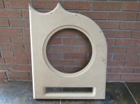
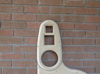
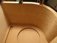
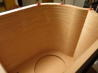
The woofer boxes are coming along.
The front baffle is still just 1" MDF. I don't believe this will stay. It'll be fine for testing. I will have to glue and screw some leftover hardwood planks to the backside. These will hold the screws better.
The curved portion of the sidewall is 1.5" thick. This will be fine. I will torch some roofing membrane to this side, and cover with Roxul 'sound' insulation.
The bottom is 3/4" hardwood plywood. This will hold floor spikes a lot better than MDF. Torch a layer of roofing stuff. Build the slot port channel.
The large MDF side panel will need the membrane, a layer of 3/4" hardwood plywood, bracing, then sound insulation.
Attachments
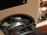
The Acoustic Elegance TD6M has a well documented low spot around 700Hz. This coincides with a slight blip in the impedance measurement.
Something I know I have to do is chamfer the baffles inner driver edge. I went back and read Troels article on chamfering. I tried a 'roundover', and that was wrong. I'm looking forward to trying to chamfer with a finished box????
The following observations only help above 625Hz. Building speakers is fun. Repeat over and over.
Picture 1) This shows the frequency response (in circuit) of the driver with sorbothane wrapped around the magnet, and the stock unit. The sorbothane trace has a pronounced bump. This won't work.
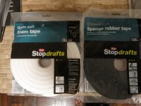
Picture 2) I bought both open cell, and closed cell foam.
Picture 3) A picture of the Sorbothane wrapped around the magnet.
Picture 4) Stock
Picture 5) I started with the white open cell foam. It's wrapped around the housing just below the spider.
Picture 6) These are the measurements of the driver with open cell foam versus the stock unit. There is absolutely no change.
Picture 7) Black 'closed' cell foam.
Picture 8) Measurements using closed cell foam. It makes a definite difference. I will definitely be using this technique. There is also a trace with both the closed cell, and sorbothane. Not sure if I like this one.
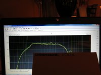
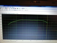
Picture 9) I've lowered the range on the graph, and applied smoothing. If I read this correctly, we're about 1.5dB between lowest and highest.
Picture 10) I've increased the range, making the smoothed line look really nice.
Something I know I have to do is chamfer the baffles inner driver edge. I went back and read Troels article on chamfering. I tried a 'roundover', and that was wrong. I'm looking forward to trying to chamfer with a finished box????
The following observations only help above 625Hz. Building speakers is fun. Repeat over and over.
Picture 1) This shows the frequency response (in circuit) of the driver with sorbothane wrapped around the magnet, and the stock unit. The sorbothane trace has a pronounced bump. This won't work.
Picture 2) I bought both open cell, and closed cell foam.
Picture 3) A picture of the Sorbothane wrapped around the magnet.
Picture 4) Stock
Picture 5) I started with the white open cell foam. It's wrapped around the housing just below the spider.
Picture 6) These are the measurements of the driver with open cell foam versus the stock unit. There is absolutely no change.
Picture 7) Black 'closed' cell foam.
Picture 8) Measurements using closed cell foam. It makes a definite difference. I will definitely be using this technique. There is also a trace with both the closed cell, and sorbothane. Not sure if I like this one.
Picture 9) I've lowered the range on the graph, and applied smoothing. If I read this correctly, we're about 1.5dB between lowest and highest.
Picture 10) I've increased the range, making the smoothed line look really nice.
Attachments
-
 IMG_0730.jpg625.3 KB · Views: 137
 -
 IMG_0727.jpg710.8 KB · Views: 116
 -
 IMG_0728.jpg653.3 KB · Views: 116
 -
 IMG_0729.jpg591 KB · Views: 138
 -
 IMG_0732.jpg673.5 KB · Views: 130
 -
 IMG_0734.jpg727.8 KB · Views: 116
 -
 IMG_0736.jpg595.2 KB · Views: 140
 -
 IMG_0739.jpg796.6 KB · Views: 138
 -
 IMG_0741.jpg945.1 KB · Views: 121
 -
 IMG_0742.jpg989 KB · Views: 114
Why every crossover should be 'Balanced'.
First a story.
At this website, in addition to others, we learn about speaker drivers. If someone thinks they have a burnt out driver, they get advice on testing. One of the ways of testing for a burnt out voice coil, is the battery test. In this test, one take a small 9V battery. Connect the +ve terminal of the battery to the +ve driver post, connect the -ve terminal of the battery to the -ve driver post. If the driver is still good, the driver will push out, and stay there. The voice coil of the driver is resisting the current and voltage from the battery. The driver will not move back to center until the battery is removed, or drained. If you now reverse the battery, so the -ve battery terminal is now on the +ve driver lead, and the +ve connected to the -ve, the driver will now move 'in'. The driver will move 'in' the same distance as it moved out.
If we can switch back and forth between +ve and -ve really fast, like 1000 times per second, we will produce a 1000Hz tone.
The voice coil of the speaker driver, adjacent to a magnet, does only one of two things. It either moves in, or it moves out. There is no current flow through the driver. The driver is not part of the circuit. It is simply a load at the end of two wires. It moves one way with a +ve signal, and another with -ve.
If someone was to draw a proper circuit diagram of the driver, it would not be represented by a simple resistor. It would be drawn with zener diodes, and a resistor. Dare I say a speaker driver behaves like a full wave bridge rectifier?
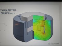
Picture 1) A driver magnet. It is static. It simply forces the voice coil to move when a current is applied.
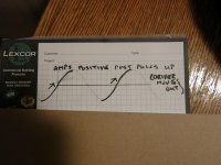
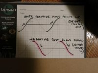
Picture 2) The positive binding post of an amplifier only manipulates the rising portion of a waveform. +ve pushes the driver out.
Picture 3) The negative binding post of an amplifier only manipulates the falling portion of a waveform. -ve pushes the driver in.
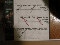
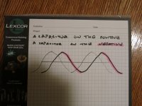
Picture 4) I finally get to the 'balanced' explanation (took long enough). A capacitor shifts voltage by -90 degrees. This means the voltage now lags the amperage. The +ve terminal of a speaker driver is only manipulated by the +ve portion of the signal. That's it!!!!!!. It's shifted.
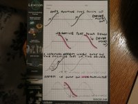
Picture 5) If the capacitor is only on the -ve terminal, the negative signal is shifted.
Picture 6) Bingo. If there is a capacitor on the +ve leg, and a cap on the -ve. The driver sees a perfect waveform.
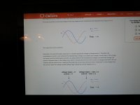
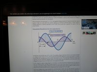
Picture 7) A smarter person than I giving a better explanation.
Picture 8) For the mathematically gifted.
Again, someone else proved this mathematically. I just can't find the link.
First a story.
At this website, in addition to others, we learn about speaker drivers. If someone thinks they have a burnt out driver, they get advice on testing. One of the ways of testing for a burnt out voice coil, is the battery test. In this test, one take a small 9V battery. Connect the +ve terminal of the battery to the +ve driver post, connect the -ve terminal of the battery to the -ve driver post. If the driver is still good, the driver will push out, and stay there. The voice coil of the driver is resisting the current and voltage from the battery. The driver will not move back to center until the battery is removed, or drained. If you now reverse the battery, so the -ve battery terminal is now on the +ve driver lead, and the +ve connected to the -ve, the driver will now move 'in'. The driver will move 'in' the same distance as it moved out.
If we can switch back and forth between +ve and -ve really fast, like 1000 times per second, we will produce a 1000Hz tone.
The voice coil of the speaker driver, adjacent to a magnet, does only one of two things. It either moves in, or it moves out. There is no current flow through the driver. The driver is not part of the circuit. It is simply a load at the end of two wires. It moves one way with a +ve signal, and another with -ve.
If someone was to draw a proper circuit diagram of the driver, it would not be represented by a simple resistor. It would be drawn with zener diodes, and a resistor. Dare I say a speaker driver behaves like a full wave bridge rectifier?
Picture 1) A driver magnet. It is static. It simply forces the voice coil to move when a current is applied.
Picture 2) The positive binding post of an amplifier only manipulates the rising portion of a waveform. +ve pushes the driver out.
Picture 3) The negative binding post of an amplifier only manipulates the falling portion of a waveform. -ve pushes the driver in.
Picture 4) I finally get to the 'balanced' explanation (took long enough). A capacitor shifts voltage by -90 degrees. This means the voltage now lags the amperage. The +ve terminal of a speaker driver is only manipulated by the +ve portion of the signal. That's it!!!!!!. It's shifted.
Picture 5) If the capacitor is only on the -ve terminal, the negative signal is shifted.
Picture 6) Bingo. If there is a capacitor on the +ve leg, and a cap on the -ve. The driver sees a perfect waveform.
Picture 7) A smarter person than I giving a better explanation.
Picture 8) For the mathematically gifted.
Again, someone else proved this mathematically. I just can't find the link.
Attachments
- Status
- This old topic is closed. If you want to reopen this topic, contact a moderator using the "Report Post" button.
- Home
- Loudspeakers
- Multi-Way
- 4-Way Series Crossover. Accuton and Acoustic Elegance Drivers