The driver is really flat up until past 3kHz, but the chamber resonances make sense. Perhaps Bill can chime in at some point. Eventually I'll measure them myself, but that will take a while. Still sourcing parts and mostly looking into how to best print the waveguide.
I'm also in the process of making one of these and am struggling a bit understanding the crossover. Why the notches in the lowpass of the 6FE100's?
In a unity horn, there are peaks in the output of the midrange above the acoustic lowpass.
IE, the midranges may be rolling off at 1500hz, acoustically, but peaks at 3khz and 6khz are commonly seen.
The driver is really flat up until past 3kHz, but the chamber resonances make sense. Perhaps Bill can chime in at some point. Eventually I'll measure them myself, but that will take a while. Still sourcing parts and mostly looking into how to best print the waveguide.
Bill can tell you the exact reason but the driver will not be flat up to 3K when put in a practical bandpass enclosure. You can simulate the response in various different programs with hornresp being an obvious one. By estimating the volume of the throat chamber formed between the cone and the enclosure or even meausring it with rice on your actual waveguide with speaker mounted.
Every bandpass has a peak before a sharp rolloff which is usually much lower than the driver could be in free air. This acoustic lowpass filter effect can be quite useful. Changing the volume of air in front of the cone and the size of the port which change the response the comes out.
That makes total sense, thanks guys. Interesting that the mids don't appear to exhibit this (at least not to an extent that would require fixing in the xover).
The mids have a volume plug to reduce the air in front of the cone, with a small volume of air and a short port the effect is much reduced and can be tuned to be virtually non existent. Much harder to do that with a woofer.

Curious as to why you printed the old version instead of the revised version without the woofer ports.
Nice work people
I have a large format printer, just need help setting it up. When I bought it last December, tried to get it working, but I failed. Lol
Now my wife uses my audio room as her office as she works from home full time
If anyone is near Daytona Beach and knows how to set these baby’s up. Pm me please
I have a large format printer, just need help setting it up. When I bought it last December, tried to get it working, but I failed. Lol
Now my wife uses my audio room as her office as she works from home full time
If anyone is near Daytona Beach and knows how to set these baby’s up. Pm me please
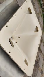
After a lot of sanding and filling holes and painting and sanding some more, I've finally gotten to a finish that I think is adequate. Next up is speaker mounting and crossover assembly.
From what I have seen this waveguide has very nice bandpass for mids.
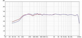
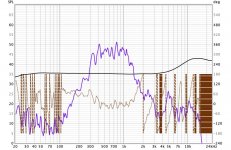
I finally got around to tinkering with this as well. Everything was done super quick and dirty, I mostly wanted to see if other woofers would work as well. The measurement angles are only approximate with a protractor held to the box, so nothing to take too serious. The crossover is done with a first gen low end minDSP through an ancient Denon multichannel receiver and just a couple of standard filters, no adjusting or refining whatsoever. The drivers are Faital 6FE100 and 6RS140 respectively, Celestion TF0410MR and Faital 108R.
The measurements are
1) the whole speaker 6FE100 vs 6RS140 on axis with ERB smoothing
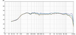
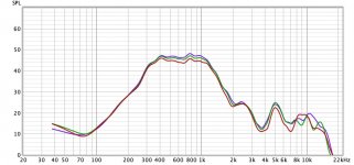
2) the whole speaker with 6RS140 at 0, 15 and 30 degrees ERB
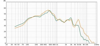
3) the mids alone with 1/24 smoothing on axis
4) the mids a 0, 15 and 30 degrees ERB
5) 6FE100 vs 6RS140 raw on axis ERB
It seems to me the 6RS140 works just as well and is simply the better driver (not judging any sound quality differences) plus (important for me) happy with a much smaller box.
The measurements are
1) the whole speaker 6FE100 vs 6RS140 on axis with ERB smoothing
2) the whole speaker with 6RS140 at 0, 15 and 30 degrees ERB
3) the mids alone with 1/24 smoothing on axis
4) the mids a 0, 15 and 30 degrees ERB
5) 6FE100 vs 6RS140 raw on axis ERB
It seems to me the 6RS140 works just as well and is simply the better driver (not judging any sound quality differences) plus (important for me) happy with a much smaller box.
Attachments
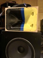
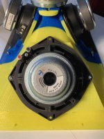
This is what the thing with its 40 liter box looks like. The 18-inch cabs are only used as stands, but ultimately that's my goal with this. Closed box on top of a big woofer. As a full speaker the 6FE100 appears to have more bass and is easier to tune BR, but does need a bigger box.
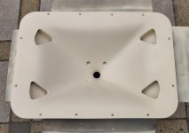
Regarding the 6RS140 the waveguide design should really be changed though. As it is now, the woofers are only held by two screws. Fine for testing but not for the actual speaker. Being completely ignorant when it comes to dealing with STL files, I have so far failed at editing the STL to add a bit of material on the back of the waveguide to add two more screws. I tried TinkerCAD, is there better software for this? I imagine this to be trivial and I'm just not getting it. This modification would then allow pretty much any 6-inch woofer to be used as the 6RS140 uses the standard hole radius.
Regarding the 6RS140 the waveguide design should really be changed though. As it is now, the woofers are only held by two screws. Fine for testing but not for the actual speaker. Being completely ignorant when it comes to dealing with STL files, I have so far failed at editing the STL to add a bit of material on the back of the waveguide to add two more screws. I tried TinkerCAD, is there better software for this? I imagine this to be trivial and I'm just not getting it. This modification would then allow pretty much any 6-inch woofer to be used as the 6RS140 uses the standard hole radius.
Attachments
Best and free for manipulating STLs is IMHO Blender. Very steep learning curve though. I used it once to change certain area thickness of a complicated STL file. The advantage is that you can manipulate the mesh directly. Importing to CAD is very problematic, I also did some basic changes in Fusion360, but it was painful. I cannot offer any more advice on how to do this as I have not explored Blender further yet.
You could create an add in piece and glue it to the exiting waveguide. As said before altering STL's is a total pain.
Fusion has a new mesh workspace that allows you to do more than before. You could plane cut the waveguide model in sections around where the joins need to be and convert those sections into solid triangulated surfaces with the Convert mesh command. This is prone to crashing if the model has a lot of triangles. The files could be cut in meshmixer too but the plane cut tool is a little harder to get right for me.
You can then create sketches by drawing lines or curves using the points from the model as references or you can create a larger block for the mount and cut or intersect the body with the converted surface.
Some images and explanation from a prior version of Fusion here might help where I cut a block with a whole waveguide STL
3D Modeling Tips and Tricks
Thanks guys, this does sound like an uphill battle though, I'm having a hard time even following the nomenclature. I think I'm better off glueing pieces of wood to the waveguide. Will take some time and filing etc, but should ultimately be stronger as well (they can be screwed on from the front with counter sunk screws too since the front of the waveguide will ultimately be covered with epoxy).
Something different altogether is baffling me a little: my (admittedly crude) measurements show a widening from roughly 2k to 8k. The bump at 3,5k on the 15deg curve might be just a mistake on my part, but the general trend is visible in Bill's measurements as well. It's clearly in the passband of the compression driver only and shows up with different CD's. Any idea what's causing that?
Something different altogether is baffling me a little: my (admittedly crude) measurements show a widening from roughly 2k to 8k. The bump at 3,5k on the 15deg curve might be just a mistake on my part, but the general trend is visible in Bill's measurements as well. It's clearly in the passband of the compression driver only and shows up with different CD's. Any idea what's causing that?
Diffraction and the native pattern of the waveguide.Any idea what's causing that?
Not much I can do about the native pattern. When it comes to diffraction, I can definitely improve on the transition from the CD to the waveguide and add roundovers at the mouth. In general, are the taps in MEH's a serious sourse of diffraction?
Smoothing the transition from the horn to the box and rounding over the edges of the box as much as possible could make some difference in that range.
The taps are for sure a source of diffraction, how much and how audible it is, is not as clear.
The taps are for sure a source of diffraction, how much and how audible it is, is not as clear.
- Home
- Loudspeakers
- Multi-Way
- 3D printed 3-way Unity waveguide home audio speaker